
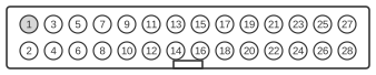
 28 PIN IDC MALE at the SUN SPARC engine motherboards.
The SROMBOlite connector is a 28-pin IDC male header found on Sun SPARCengine CP 1500 motherboards, a CompactPCI SBus product from the late 1990s. Like its larger sibling SROMBO (34-pin), it is an internal factory interface used for programming and testing the expansion ROM (“ROMBO”) chip and associated logic — it is not a user-accessible expansion port. It carries an 8-bit Expansion Bus (EB) with 8 address lines (EB_ADR<0–7>), 8 data lines (EB_DAT<0–7>), read/write strobes, chip-select signals, and additional control lines for the on-board SCC serial controller; the reduced address space of 8 lines (versus 20 on the SROMBO) reflects the smaller address range required by the CP 1500’s bus controller architecture. All signals operate at TTL-compatible +5 V logic.
| Pin | Name |
|---|---|
| 1 | +5V |
| 2 | GND |
| 3 | EB_RD_L |
| 4 | EB_WR_L |
| 5 | EB_SCC_CS_L |
| 6 | EB_LATCH |
| 7 | EB_RDY_L |
| 8 | EB_DAT<0> |
| 9 | EB_DAT<1> |
| 10 | EB_DAT<2> |
| 11 | EB_DAT<3> |
| 12 | BRST_L |
| 13 | EB_DAT<4> |
| 14 | EB_DAT<5> |
| 15 | EB_DAT<6> |
| 16 | EB_DAT<7> |
| 17 | ROMBO_CS_L |
| 18 | EB_ADR<0> |
| 19 | EB_ADR<1> |
| 20 | EB_ADR<2> |
| 21 | EB_ADR<3> |
| 22 | SYNC_SER_IRQ_L |
| 23 | EB_ADR<4> |
| 24 | EB_ADR<5> |
| 25 | EB_ADR<6> |
| 26 | EB_ADR<7> |
| 27 | +5V |
| 28 | GND |
Notes
- The SROMBOlite is an internal factory/test header and is not intended for end-user use or field upgrades.
- The connector is a standard 28-pin IDC (Insulation Displacement Connector) male, fitted on the SPARCengine CP 1500 motherboard.
- All logic signals operate at TTL-compatible +5 V; the bus is passive and has no hot-plug capability.
- The “EB_” prefix on signal names stands for “Expansion Bus”, distinguishing CP 1500 nomenclature from the plain ADR/DAT naming used on the SROMBO (Ultra AXmp).
- The connector provides access to the ROMBO expansion ROM (via ROMBO_CS_L) and the on-board SCC serial controller (via EB_SCC_CS_L), reflecting the dual factory-test role of the interface.
Signals
- +5V — 5 V DC power supply (pins 1 and 27).
- GND — Ground return (pins 2 and 28).
- EB_RD_L — Active-low read strobe; asserted by the bus master to initiate a read cycle on the Expansion Bus.
- EB_WR_L — Active-low write strobe; asserted to initiate a write cycle on the Expansion Bus.
- EB_SCC_CS_L — Active-low chip select for the on-board SCC (Serial Communications Controller); enables the serial controller during factory test.
- EB_LATCH — Address/data latch signal; used to demultiplex or hold address information on the Expansion Bus.
- EB_RDY_L — Active-low ready signal; asserted by a target device to indicate it has completed a bus cycle (wait-state insertion).
- EB_DAT<0–7> — 8-bit bidirectional data bus (pins 8–11 and 13–16).
- BRST_L — Active-low burst signal; indicates a burst transfer mode on the Expansion Bus.
- ROMBO_CS_L — Active-low chip select for the ROMBO expansion ROM device; the primary programming/access signal for the boot ROM.
- EB_ADR<0–7> — 8-bit address bus (pins 18–21 and 23–26); selects one of up to 256 addressable locations within the targeted device’s address space.
- SYNC_SER_IRQ_L — Active-low synchronous serial interrupt request; signals a pending interrupt from the SCC or associated serial logic to the host processor.
References
- IEEE 1496-1993 — IEEE Standard for a Chip and Module Interconnect Bus: SBus
- SUN SPARCengine CP 1500 Manual (source cited by HwB; primary documentation for this connector)