
The GeekPort is a proprietary general-purpose I/O connector designed by Be Inc. for the BeBox personal computer, produced between 1995 and 1996. It uses an uncommon 37-pin D-SUB shell — chosen deliberately to avoid accidental misconnection with standard PC ports — and provides two independent 8-bit bidirectional TTL digital ports, four 12-bit analogue inputs via a Maxim MAX186 ADC, four 8-bit analogue outputs via a Maxim MAX505 DAC, and ±12V and +5V power rails. The connector was documented in the Be Inc. BeBox GeekPort DeviceKit and was intended to give hardware hobbyists direct access to the computer’s I/O subsystem without additional interface cards.
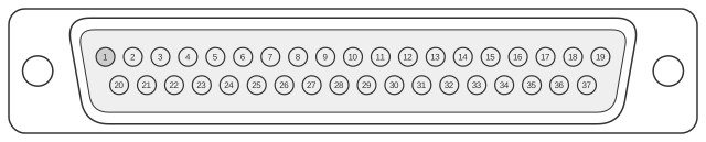 37 PIN D-SUB MALE CONNECTOR at the device
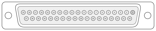 37 PIN D-SUB FEMALE CONNECTOR at the computer
| Pin | Name | Description | Dir |
|---|---|---|---|
| 1 | GND | Ground | |
| 2 | A1 | Digital A 1 | IN/OUT |
| 3 | A3 | Digital A 3 | IN/OUT |
| 4 | A5 | Digital A 5 | IN/OUT |
| 5 | A7 | Digital A 7 | IN/OUT |
| 6 | GND | Ground | |
| 7 | +5V | +5 VDC | |
| 8 | GND | Ground | |
| 9 | +12V | +12 VDC | |
| 10 | GND | Ground | |
| 11 | -12V | -12 VDC | |
| 12 | GND | Ground | |
| 13 | +5V | +5 VDC | |
| 14 | GND | Ground | |
| 15 | B0 | Digital B 0 | IN/OUT |
| 16 | B2 | Digital B 2 | IN/OUT |
| 17 | B4 | Digital B 4 | IN/OUT |
| 18 | B6 | Digital B 6 | IN/OUT |
| 19 | GND | Ground | |
| 20 | A0 | Digital A 0 | IN/OUT |
| 21 | A2 | Digital A 2 | IN/OUT |
| 22 | A4 | Digital A 4 | IN/OUT |
| 23 | A6 | Digital A 6 | IN/OUT |
| 24 | AIref | Analog In Reference | IN |
| 25 | A2D1 | Analog In 1 | IN |
| 26 | A2D2 | Analog In 2 | IN |
| 27 | A2D3 | Analog In 3 | IN |
| 28 | A2D4 | Analog In 4 | IN |
| 29 | D2A1 | Analog Out 1 | OUT |
| 30 | D2A2 | Analog Out 2 | OUT |
| 31 | D2A3 | Analog Out 3 | OUT |
| 32 | D2A4 | Analog Out 4 | OUT |
| 33 | AOref | Analog Out Reference | IN |
| 34 | B1 | Digital B 1 | IN/OUT |
| 35 | B3 | Digital B 3 | IN/OUT |
| 36 | B5 | Digital B 5 | IN/OUT |
| 37 | B7 | Digital B 7 | IN/OUT |
Signals
- A0–A7 — Digital port A, eight bidirectional TTL lines (0–5 V). A0–A3 occupy pins 20–23; A4–A7 occupy pins 2–5.
- B0–B7 — Digital port B, eight bidirectional TTL lines (0–5 V). B0–B3 occupy pins 15–18; B4–B7 occupy pins 34–37. Odd-numbered bits share pins with even-numbered bits in interleaved fashion.
- A2D1–A2D4 — Four analogue input channels (pins 25–28) driven into a Maxim MAX186 12-bit serial ADC. The MAX186 operates on a +5 V single supply or ±5 V dual supply with an internal 4.096 V reference.
- AIref — Analogue input reference voltage (pin 24); sets the full-scale range for the ADC inputs.
- D2A1–D2A4 — Four analogue output channels (pins 29–32) sourced from a Maxim MAX505 quad 8-bit DAC with independent reference inputs per channel and a +5 V supply.
- AOref — Analogue output reference input (pin 33); sets the reference for the DAC outputs.
- +5V — +5 VDC supply on pins 7 and 13.
- +12V — +12 VDC supply on pin 9.
- -12V — −12 VDC supply on pin 11.
- GND — Ground returns on pins 1, 6, 8, 10, 12, 14, and 19 (seven pins total).
Notes
- Direction is computer relative to device.
- The connector shell is a 37-pin D-SUB: male (pins) on the external device, female (sockets) on the BeBox. This shell size is deliberately non-standard for PC peripherals to prevent misconnection.
- The digital ports (A and B) are TTL-compatible and bidirectional; signal direction is software-controlled.
- The analogue inputs use the Maxim MAX186 (8-channel, 12-bit, serial-interface ADC). Only four of the eight MAX186 channels are routed to the GeekPort.
- The analogue outputs use the Maxim MAX505 (quad 8-bit DAC with four independent references).
- The ±12 V rails allow peripheral circuits requiring bipolar analogue supply; the two +5 V pins provide additional current capacity for digital loads.
- Be Inc. ceased operations in 2001; original GeekPort DeviceKit documentation from be.com is no longer available directly and survives only in third-party archives.