
 50 PIN HI-DENSITY D-SUB FEMALE at the controller and devices
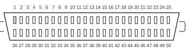 50 PIN HI-DENSITY D-SUB MALE at the cable
The SCSI-II External Hi D-Sub is the shielded, high-density 50-pin D-Sub (HD-50) connector used for external narrow SCSI-2 cabling. Defined in ANSI X3.131-1994 (SCSI-2) and carried forward in the SPI-2 physical-layer standard (INCITS 302-1998), it replaced the bulkier Centronics CN-50 for external use, offering contacts at 1.27 mm pitch in a compact D-shell housing. The connector carries an 8-bit data bus (DB0–DB7) with odd parity, plus the nine SCSI control signals, and uses single-ended (SE) 5 V signalling, limiting maximum cable length to 6 m (or 3 m for Ultra SCSI). Pins 1–25 are all ground, providing effective shielding for each signal return path; termination power is supplied on pin 38 (TERMPWR/TMPWR).
| Pin | Name | Dir | Description |
|---|---|---|---|
| 1-25 | GND | - | Ground |
| 26 | DB0 | IN/OUT | Data Bus 0 |
| 27 | DB1 | IN/OUT | Data Bus 1 |
| 28 | DB2 | IN/OUT | Data Bus 2 |
| 29 | DB3 | IN/OUT | Data Bus 3 |
| 30 | DB4 | IN/OUT | Data Bus 4 |
| 31 | DB5 | IN/OUT | Data Bus 5 |
| 32 | DB6 | IN/OUT | Data Bus 6 |
| 33 | DB7 | IN/OUT | Data Bus 7 |
| 34 | PARITY | IN/OUT | Data Parity (odd Parity) |
| 35 | GND | - | Ground |
| 36 | GND | - | Ground |
| 37 | GND | - | Ground |
| 38 | TMPWR | IN/OUT | Termination Power |
| 39 | GND | - | Ground |
| 40 | GND | - | Ground |
| 41 | /ATN | IN | Attention |
| 42 | n/c | - | Not connected |
| 43 | /BSY | IN/OUT | Busy |
| 44 | /ACK | IN | Acknowledge |
| 45 | /RST | IN/OUT | Reset |
| 46 | /MSG | OUT | Message |
| 47 | /SEL | IN/OUT | Select |
| 48 | /C/D | OUT | Control/Data |
| 49 | /REQ | OUT | Request |
| 50 | /I/O | OUT | Input/Output |
Notes
- Direction is device relative to the bus (other devices).
- This is a single-ended (SE) connector; SE uses 5 V logic and a single signal line driven against ground. Maximum cable length is 6 m for Slow/Fast SCSI or 3 m for Ultra SCSI.
- SE is electrically incompatible with High Voltage Differential (HVD). Connecting SE and HVD devices on the same bus will cause damage. Low Voltage Differential (LVD/MSE) devices can detect the bus type via the DIFFSENSE signal and downgrade to SE mode automatically, but doing so limits the entire bus to SE speeds.
- Two terminators are required per SCSI bus segment, fitted at the two physical endpoints only. Passive termination (220/330 Ω resistors) is acceptable only for Slow SCSI (5 MB/s maximum); active termination is required for Fast SCSI and above.
- The female HD-50 socket is fitted to the controller and to each device; the male HD-50 plug is on the cable.
- The connector uses a 1.27 mm contact pitch in a shielded D-shell, making it mechanically incompatible with the older Centronics CN-50 (2.16 mm pitch) external connector despite carrying identical electrical signals.
Signals
- DB0–DB7 — 8-bit parallel data bus (narrow SCSI); active-low, all bidirectional.
- PARITY — odd parity bit for DB0–DB7; bidirectional; covers the eight data lines.
- /ATN — Attention; driven by the initiator to request a Message Out phase from the target.
- n/c — Pin 42 is not connected; reserved.
- /BSY — Busy; asserted by any device currently using the bus or during arbitration.
- /ACK — Acknowledge; asserted by the initiator to handshake each byte transfer with /REQ.
- /RST — Reset; asserted to reset all devices on the SCSI bus immediately.
- /MSG — Message; asserted by the target during Message phases.
- /SEL — Select; used during the Selection and Reselection phases to address a specific device.
- /C/D — Control/Data; indicates whether the current transfer carries control information (high) or data (low).
- /REQ — Request; asserted by the target to initiate each byte handshake with /ACK.
- /I/O — Input/Output; indicates data transfer direction relative to the initiator (asserted = input to initiator).
- TMPWR (TERMPWR) — Termination power (pin 38); supplies voltage to terminator circuits at the bus endpoints.
- GND — Ground; pins 1–25 and selected higher-numbered pins are all signal-return grounds, one per signal line.
References
- SCSI Parallel Interface - 2 (SPI-2) Working Drafts Index
- SCSI Parallel Interface - 5 (SPI-5) Working Drafts Index
- 68-Pin SCSI Cable Pinout for SE and HVD Interface
- LVD, SE, HVD SCSI Compatibility — Or Not
- SCSI FAQ Part 4 — Cabling, Termination, and Connector Technical Answers
- SCSI-2 Specification Section 5: Physical Characteristics (ANSI X3.131-1994 transcription)
- SCSI Revision Levels | Seagate Support