
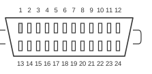
 IEEE 488 24 PIN MALE CONNECTOR
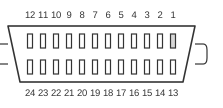 IEEE 488 24 PIN FEMALE CONNECTOR
The IEEE 488 bus — also known as GPIB (General Purpose Interface Bus) or HP-IB (Hewlett-Packard Interface Bus) — is a parallel instrumentation interface originally developed by Hewlett-Packard around 1965 and first published in the October 1972 HP Journal. It was standardised as IEEE 488 in 1975, revised in 1978, and redesignated IEEE 488.1 in 1987 when IEEE 488.2 added standard codes, formats, and common commands; the unified IEC equivalent is IEC 60488-1:2004. The bus uses a 24-pin Amphenol 57-series micro-ribbon connector and supports up to 15 devices per segment over a maximum cable run of 20 m, with a standard transfer rate of up to 1 MB/s (the HS-488 extension achieves up to 8 MB/s). Its three-wire source-acceptor handshake (DAV/NRFD/NDAC) allows simultaneous multicast to multiple listeners at the rate of the slowest, making it well suited to laboratory instrument control.
| PIN | Signal | Description |
|---|---|---|
| 1 | Data I/O 1 | |
| 2 | Data I/O 2 | |
| 3 | Data I/O 3 | |
| 4 | Data I/O 4 | |
| 5 | EOI | End Or Identify has two uses. EOI is asserted on the last byte of a data transfer. This signals all devices that no more data should be expected on the transfer. |
| 6 | DAV | Data Valid is a handshake line indicating that the active talker has placed data on the data lines. |
| 7 | NRFD | Not Ready For Data is a handshake line indicating that one or more active listeners is not ready for more data. Note the active talker should then wait before sending any more data on the bus. |
| 8 | NDAC | Not Data Accepted is a handshake line indicating that one or more active listeners has not accepted the current data byte. Note the active talker should leave the current byte asserted on the data lines until it has been accepted or timed out. |
| 9 | IFC | Interface Clear is under the exclusive control of the system controller. When it is active high all devices on the bus are returned to an idle state and the bus is cleared |
| 10 | SRQ | Service Request can be set by a device on the interface to indicate it is in need of service. SRQ could be set at the completion of a task. E.g. finished doing a measurement, or when an error has occurred. |
| 11 | ATN | Attention is used primarily to differentiate between command mode and data mode. When ATN is TRUE (I.E. Active high) information on the bus is a command and when ATN is FALSE (Active LOW) the information on the bus is data. |
| 12 | SHIELD GROUND | (Earth) |
| 13 | Data I/O 5 | |
| 14 | Data I/O 6 | |
| 15 | Data I/O 7 | |
| 16 | Data I/O 8 | |
| 17 | REN | Remote Enable may be set by the system controller to allow other devices to operate in remote mode. |
| 18 | P/O Twisted pair with 6 | |
| 19 | P/O Twisted pair with 7 | |
| 20 | P/O Twisted pair with 8 | |
| 21 | P/O Twisted pair with 9 | |
| 22 | P/O Twisted pair with 10 | |
| 23 | P/O Twisted pair with 11 | |
| 24 | SIGNAL GROUND |
Signals
- DIO1–DIO8 (pins 1–4, 13–16) — Eight bidirectional data lines using TTL active-low, open-collector (wired-OR) signalling; carry both data bytes and bus commands depending on the state of ATN.
- DAV (pin 6) — Data Valid; asserted by the active talker to indicate stable, valid data on the DIO lines.
- NRFD (pin 7) — Not Ready For Data; wired-OR line asserted by any listener that is not yet ready to accept a new byte; the talker must wait whilst this line is asserted.
- NDAC (pin 8) — Not Data Accepted; wired-OR line held asserted until every active listener has accepted the current byte, enabling reliable multicast to multiple devices simultaneously.
- EOI (pin 5) — End Or Identify; dual-purpose: asserted by a talker on the final byte of a multi-byte transfer to mark the end of the message, or asserted by the Controller during a parallel poll (Identify).
- IFC (pin 9) — Interface Clear; driven exclusively by the system Controller to reset all devices to their idle state and clear the bus.
- SRQ (pin 10) — Service Request; wired-OR line asserted by any device requiring attention from the Controller, analogous to an interrupt request.
- ATN (pin 11) — Attention; asserted by the Controller to indicate that the DIO lines carry bus commands (addresses or universal commands) rather than device data.
- REN (pin 17) — Remote Enable; asserted by the Controller to allow addressed devices to switch from local front-panel operation to remote (programmatic) control.
- Pins 18–23 — Twisted-pair return conductors, one per handshake and management signal (paired with pins 6–11 respectively) to reduce noise on longer cable runs.
- Pin 12 — Shield ground (chassis earth).
- Pin 24 — Signal ground reference.
Notes
The IEEE 488 connector is a 24-way Amphenol 57-series micro-ribbon (also known as a Champ connector). Cables use a back-to-back male-female arrangement that allows instruments to be daisy-chained; the locking screws follow the M3.5×0.6 metric thread standard. An alternative 25-pin D-sub connector was permitted under IEC 60625-1 but was never widely adopted and has no market presence.
All signal lines are TTL-compatible, active-low, and use open-collector drivers to achieve the wired-OR behaviour necessary for multi-device arbitration. The bus is entirely asynchronous — transfer speed is governed by the three-wire handshake rather than a clock, so it naturally adapts to the slowest device on the bus.
A maximum of 15 devices may be connected per bus segment. No individual cable run between adjacent instruments should exceed 4 m; average inter-device spacing should be no more than 2 m; and the total cable length must not exceed 20 m. The standard data rate is up to 1 MB/s; the HS-488 amendment raises this to a theoretical maximum of 8 MB/s, but all devices on the segment must support HS-488 to achieve this rate.
Primary addresses are in the range 0–30 (31 possible addresses per bus); each device may additionally have secondary (sub-)addresses in the same range, giving a theoretical maximum of 961 addressable entities. Typical real-world throughput in instrument systems is 250–500 kB/s.
IEEE 488, GPIB, and HP-IB are the same electrical interface. The current unified international standard is IEC 60488-1:2004, which supersedes both IEEE 488.1-1987 and IEC 60625-1.