
SCSI = Small Computer System Interface
SCSI-3 External Hi D-Sub Low Voltage Differential/Single Ended (LVD/SE)
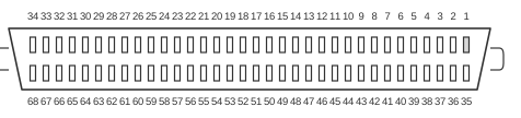 68 pin hi-density D-SUB female connector at the controller and devices.
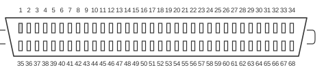 68 pin hi-density D-SUB male connector at the cable.
The 68-pin high-density D-Sub (DH68) connector is the standard physical interface for Wide SCSI, carrying a 16-bit data bus (DB0–DB15) plus two parity lines and the full complement of SCSI control signals. Defined in SCSI-2 (ANSI X3.131-1994) and carried forward through SCSI-3 SPI-2 (INCITS 302-1998) to SPI-5 (INCITS 367-2003), it supports Single-Ended (SE), High Voltage Differential (HVD), and Low Voltage Differential / Multimode Single-Ended (LVD/MSE) signalling. LVD/MSE devices automatically detect the bus type via the DIFFSENSE pin and switch between LVD and SE operation accordingly, though connecting any SE device to an LVD bus downgrades the entire bus to SE mode.
| Pin | Name | Dir | Description |
|---|---|---|---|
| 1 | GND | - | Ground |
| 2 | GND | - | Ground |
| 3 | GND | - | Ground |
| 4 | GND | - | Ground |
| 5 | GND | - | Ground |
| 6 | GND | - | Ground |
| 7 | GND | - | Ground |
| 8 | GND | - | Ground |
| 9 | GND | - | Ground |
| 10 | GND | - | Ground |
| 11 | GND | - | Ground |
| 12 | GND | - | Ground |
| 13 | GND | - | Ground |
| 14 | GND | - | Ground |
| 15 | GND | - | Ground |
| 16 | GND | - | Ground |
| 17 | TERMPWR | IN/OUT | Termination Power |
| 18 | TERMPWR | IN/OUT | Termination Power |
| 19 | RES | - | Reserved |
| 20 | GND | - | Ground |
| 21 | GND | - | Ground |
| 22 | GND | - | Ground |
| 23 | GND | - | Ground |
| 24 | GND | - | Ground |
| 25 | GND | - | Ground |
| 26 | GND | - | Ground |
| 27 | GND | - | Ground |
| 28 | GND | - | Ground |
| 29 | GND | - | Ground |
| 30 | GND | - | Ground |
| 31 | GND | - | Ground |
| 32 | GND | - | Ground |
| 33 | GND | - | Ground |
| 34 | GND | - | Ground |
| 35 | -DB12 | IN/OUT | -Data Bus 12 |
| 36 | -DB13 | IN/OUT | -Data Bus 13 |
| 37 | -DB14 | IN/OUT | -Data Bus 14 |
| 38 | -DB15 | IN/OUT | -Data Bus 15 |
| 39 | -DPB1 | IN/OUT | -Data Bus Parity (odd Parity) |
| 40 | -DB0 | IN/OUT | -Data Bus 0 |
| 41 | -DB1 | IN/OUT | -Data Bus 1 |
| 42 | -DB2 | IN/OUT | -Data Bus 2 |
| 43 | -DB3 | IN/OUT | -Data Bus 3 |
| 44 | -DB4 | IN/OUT | -Data Bus 4 |
| 45 | -DB5 | IN/OUT | -Data Bus 5 |
| 46 | -DB6 | IN/OUT | -Data Bus 6 |
| 47 | -DB7 | IN/OUT | -Data Bus 7 |
| 48 | -DPB | IN/OUT | -Data Bus Parity (odd Parity) |
| 49 | GND | - | Ground |
| 50 | GND | - | Ground |
| 51 | TERMPWR | IN/OUT | Termination Power |
| 52 | TERMPWR | IN/OUT | Termination Power |
| 53 | RES | - | Reserved |
| 54 | GND | - | Ground |
| 55 | -ATN | IN | -Attention |
| 56 | GND | - | Ground |
| 57 | -BSY | IN/OUT | -Bus is busy |
| 58 | -ACK | IN | -Acknowledge |
| 59 | -RST | IN/OUT | -Reset |
| 60 | -MSG | OUT | -Message |
| 61 | -SEL | IN/OUT | -Select |
| 62 | -C/D | OUT | -Control or Data |
| 63 | -REQ | OUT | -Request |
| 64 | -I/O | OUT | -In/Out |
| 65 | -DB8 | IN/OUT | -Data Bus 8 |
| 66 | -DB9 | IN/OUT | -Data Bus 9 |
| 67 | -DB10 | IN/OUT | -Data Bus 10 |
| 68 | -DB11 | IN/OUT | -Data Bus 11 |
Signals
- -DB0 – -DB15 — Active-low data bus lines for the 16-bit Wide SCSI data path; all signal names are active-low per SCSI convention.
- -DPB — Active-low odd parity for the lower data byte (DB0–DB7).
- -DPB1 — Active-low odd parity for the upper data byte (DB8–DB15).
- -ATN — Attention; asserted by the initiator to request a message phase with the target.
- -BSY — Bus Busy; asserted by any device currently using the SCSI bus.
- -ACK — Acknowledge; asserted by the initiator to confirm receipt of each data byte from the target.
- -RST — Reset; asserts a hard reset condition on the bus, returning all devices to their initial state.
- -MSG — Message; asserted by the target during the message phase to distinguish message bytes from command/data bytes.
- -SEL — Select; used by the initiator to select a target device (or by a target during reselection).
- -C/D — Control or Data; asserted by the target to indicate whether the current byte is a control (command/message/status) or data byte.
- -REQ — Request; asserted by the target to request a data transfer handshake cycle.
- -I/O — In/Out; asserted by the target to indicate the direction of data transfer (asserted = data flowing to initiator).
- TERMPWR — Termination Power; supplies +5 V to active terminators on the bus; provided by one or more devices on the bus.
- RES — Reserved; must not be driven and must be left unconnected by compliant devices.
- GND — Signal ground; the majority of pins are ground to reduce crosstalk and improve signal integrity on the wide connector.
Notes
- Direction is device-relative to bus (other devices).
- The connector uses two rows of 34 female contacts at 1.27 mm pitch (female at controller/device, male on cable).
- In Single-Ended mode, all signal lines are driven against a common ground reference; maximum cable length is 6 m for Slow/Fast SCSI and 3 m for Ultra SCSI.
- LVD/MSE devices operate at 3.3 V logic and support cable lengths up to 12 m (25 m in point-to-point configurations). They switch to SE mode automatically when a SE device is detected on the bus via the DIFFSENSE pin.
- HVD (High Voltage Differential) signalling uses complementary +/– signal pairs at 5 V logic and supports cable lengths up to 25 m, but HVD was declared obsolete in SPI-3 (INCITS 336-2000) and must not be mixed with SE or LVD devices.
- Exactly two terminators are required per bus segment, placed at the two extreme ends only. Passive termination (220/330 Ω resistors) is acceptable only for Slow SCSI (5 MB/s maximum); active termination is required for Fast SCSI and all higher speeds.
- The DIFFSENSE pin (not explicitly listed in this single-ended pinout) is used by LVD/MSE multimode devices to detect whether the bus is operating in SE or LVD mode.
- For more information see SCSI Technology.
References
- 68-Pin SCSI Cable Pinout for SE and HVD Interface
- 68-Pin SCSI Pinout for LVD/MSE SCSI
- LVD, SE, HVD SCSI Compatibility — Or Not
- SCSI FAQ Part 4 — Cabling, Termination, and Connector Technical Answers
- SCSI Parallel Interface - 2 (SPI-2) Working Drafts Index
- SCSI Parallel Interface - 5 (SPI-5) Working Drafts Index
- SCSI-2 Specification Section 5: Physical Characteristics (ANSI X3.131-1994)
- SCSI Revision Levels