
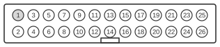
 26 PIN IDC MALE at the Video card
The VESA Feature Connector (VFC) is a 26-pin IDC (BERG) header fitted to VGA and Super VGA graphics cards, standardised by VESA and first documented by IBM as the “VGA Video Extension” in the IBM Video Subsystem Technical Reference (1992). It taps the card’s internal digital video bus, carrying eight parallel palette data bits (PD0–PD7) fed directly to the DAC, together with the dot clock, blanking, horizontal sync, and vertical sync signals. The connector allowed auxiliary adapters — such as video capture cards or MPEG decoders — to intercept or inject digital video data before it reached the DAC. Three control lines with +5 V pull-ups govern the direction of the data and clock signals, enabling either the host VGA card or the attached adapter to drive the bus.
| Pin | Name | Description |
|---|---|---|
| 1 | PD0 | DAC Pixel Data Bit 0 (PB) |
| 2 | PD1 | DAC Pixel Data Bit 1 (PG) |
| 3 | PD2 | DAC Pixel Data Bit 2 (PR) |
| 4 | PD3 | DAC Pixel Data Bit 3 (PI) |
| 5 | PD4 | DAC Pixel Data Bit 4 (SB) |
| 6 | PD5 | DAC Pixel Data Bit 5 (SG) |
| 7 | PD6 | DAC Pixel Data Bit 6 (SR) |
| 8 | PD7 | DAC Pixel Data Bit 7 (SI) |
| 9 | CLK | DAC Clock |
| 10 | BLK | DAC Blanking |
| 11 | HSYNC | Horizontal Sync |
| 12 | VSYNC | Vertical Sync |
| 13 | GND | Ground |
| 14 | GND | Ground |
| 15 | GND | Ground |
| 16 | GND | Ground |
| 17 | Select Internal Video | When high pins 1-8 are outputs, when low they are inputs. This pin has an internal pull-up |
| 18 | Select Internal Sync | When high pins 10-12 are outputs. This pin has an internal pull-up |
| 19 | Select Internal Dot Clock | When high pin 9 is an output. This pin has an internal pull-up |
| 20 | n/c | Not used |
| 21 | GND | Ground |
| 22 | GND | Ground |
| 23 | GND | Ground |
| 24 | GND | Ground |
| 25 | n/c | Not used |
| 26 | n/c | Not used |
Signals
- PD0–PD7 — Eight-bit parallel palette data bus carrying the digital pixel value clocked into the DAC on each dot-clock cycle. IBM’s documentation labels these P0–P7; the VESA VFC mapping uses PD0–PD7. When Select Internal Video is low, an auxiliary adapter drives these lines; when high, the VGA card’s internal video path drives them.
- CLK — Dot clock (DCLK); data on PD0–PD7 is latched on the rising edge. The IBM specification states the PEL clock period minimum is 28 ns. When Select Internal Dot Clock is high, the VGA card drives this line; an auxiliary adapter may supply the clock when the pin is pulled low.
- BLK — Blanking signal (BLANK); when asserted low (0 V), the DAC outputs are forced to 0 V, suppressing video during horizontal and vertical blanking intervals. Controlled by Select Internal Sync.
- HSYNC — Horizontal sync output from the VGA card, driven when Select Internal Sync is high.
- VSYNC — Vertical sync output from the VGA card, driven when Select Internal Sync is high.
- Select Internal Video (pin 17) — Active-high control with +5 V internal pull-up (IBM signal name: EVIDEO). High = VGA card drives PD0–PD7; low = auxiliary adapter drives PD0–PD7.
- Select Internal Sync (pin 18) — Active-high control with +5 V internal pull-up (IBM signal name: ESYNC). High = VGA card drives BLK, HSYNC, and VSYNC.
- Select Internal Dot Clock (pin 19) — Active-high control with +5 V internal pull-up (IBM signal name: EDCLK). High = VGA card drives CLK.
- GND (pins 13–16, 21–24) — Signal ground. Multiple ground pins are distributed across the connector to minimise ground impedance at high pixel clock rates.
- n/c (pins 20, 25, 26) — Not connected; reserved.
Notes
- The connector is a 26-pin IDC (insulation-displacement) BERG-style header. Pin 13 position serves as the mechanical key (missing pin) in the IBM VFC implementation, preventing incorrect insertion.
- All three Select lines (pins 17–19) carry +5 V internal pull-ups, so they default high if left unconnected — meaning the VGA card drives all bus signals unless an auxiliary adapter actively pulls them low.
- The IBM Video Subsystem Technical Reference specifies the analogue output settling time as a maximum of 3×T1 + 5 ns after each rising clock edge, where T1 is the PEL clock period.
- The connector became redundant with the transition to digital video standards (DVI, HDMI) in the late 1990s and is absent from modern graphics cards.