
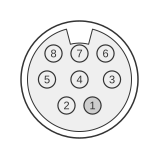
 8 pin mini-DIN female connector at the ATI videocard.
The ATI All-In-Wonder series of graphics cards, produced from the late 1990s through the mid-2000s, used an 8-pin mini-DIN connector as a dedicated video and audio input (VID IN) port on the card’s rear bracket. The connector carries composite CVBS, S-Video luminance and chrominance, and stereo audio on a single socket; a supplied breakout cable splits these signals into standard RCA and 3.5 mm jacks for connection to external sources such as VCRs and camcorders. The same 8-pin mini-DIN form factor and signal complement was also adopted by Matrox for the A/V IN connector on the Marvel G450 eTV card. At least two pin-assignment variants are known across different All-In-Wonder generations; the table below reflects the connector as documented for the ATI AIW Radeon series.
| Pin | Signal |
|---|---|
| 1 | Composite Video Signal (I/O) |
| 2 | Composite Video Ground |
| 3 | Audio Ground |
| 4 | Audio Right Signal (I/O) |
| 5 | Ground |
| 6 | Color (Chrominance) (I/O) |
| 7 | Audio Left Signal (I/O) |
| 8 | Intensity (Luminance) (I/O) |
| Shield | Ground |
Signals
- Composite Video Signal — analogue CVBS (composite video baseband signal) at approximately 1 Vpp into 75 Ω; carries luminance, chrominance, and sync combined on a single line.
- Composite Video Ground — dedicated signal return for the composite video line.
- Audio Ground — signal return shared by both stereo audio channels.
- Audio Right Signal — line-level analogue audio, right channel.
- Ground — additional circuit ground.
- Color (Chrominance) — S-Video C (chrominance) signal at approximately 0.3 Vpp into 75 Ω; carries colour information separately from luminance as per the S-Video standard (IEC 60933-5).
- Audio Left Signal — line-level analogue audio, left channel.
- Intensity (Luminance) — S-Video Y (luminance) signal at approximately 1 Vpp into 75 Ω; carries brightness and sync information.
- Shield — connector shell ground, tied to chassis.
Notes
- This connector is the video/audio input (capture) port only; it is distinct from the separate 10-pin mini-DIN VID OUT connector also present on All-In-Wonder cards.
- The breakout cable splits the 8-pin socket into individual RCA jacks for composite video input and stereo audio input, plus a 4-pin S-Video socket for Y/C input.
- At least two pin-assignment variants exist across different ATI All-In-Wonder generations. The internal 8-pin board header on the ATI AIW Radeon 9700 (per P/N 107-70336-30) labels equivalent signals as CVBS/Y-in (pin 1), Luma/Pr-in (pin 3), and Chroma/Pb-in (pin 5), indicating some models also supported component YPbPr input via the same header with an appropriate adapter.
- The Matrox Marvel G450 eTV uses an identical 8-pin mini-DIN A/V IN connector with the same signal complement (composite, S-Video Y/C, and stereo audio).
- A standard mini-DIN-8 plug is mechanically keyed; it cannot be inserted incorrectly into the socket.