
13 PIN DIN FEMALE at the Computer
13 PIN DIN MALE at the Devices
The Atari ST monitor connector is a proprietary 13-pin DIN socket found on all models in the ST family, including the 520ST, 1040ST, Mega ST, and STe. Defined in Appendix D of the Atari 520ST Owner’s Manual, it carries analogue RGB video (Red, Green, Blue), separate horizontal and vertical sync, composite video, monochrome video, monochrome detect, audio in and out, and a general-purpose output line — all on a single circular DIN connector. Compatible monitors specified by Atari include the SM124 high-resolution monochrome display and the SC1224 analogue RGB colour monitor. One notable revision exists between early and later hardware: pin 8 is Ground on the original 520ST but was changed to +12 V (10 mA) on the STe to supply peripheral circuitry.
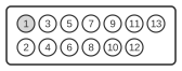
| Pin | Name | Description |
|---|---|---|
| 1 | AO | Audio Out |
| 2 | CVIDEO | Composite Video |
| 3 | CS | Clock Select |
| 4 | MD | Monochrome Detect / Clock In |
| 5 | AI | Audio In |
| 6 | G | Green |
| 7 | R | Red |
| 8 | +12V | +12 VDC (520ST has GND) |
| 9 | HSYNC | Horizontal Sync |
| 10 | B | Blue |
| 11 | MVIDEO | Monochrome Video |
| 12 | VSYNC | Vertical Sync |
| 13 | GND | Ground |
Signals
- AO — Audio output from the computer to the monitor or amplifier.
- CVIDEO — Composite video; labelled “Reserved” in the original 520ST manual but used as composite video output on configurations that include an RF modulator circuit.
- CS — General Purpose Output on the 520ST; repurposed as an External Clock Select line on the STe for switching video clock sources.
- MD — Monochrome Detect / Clock In; used by the hardware to detect whether a monochrome monitor is connected and to select the appropriate video mode.
- AI — Audio input to the computer from the monitor or an external source.
- G — Analogue Green video signal.
- R — Analogue Red video signal.
- +12V — +12 V DC supply at up to 10 mA on STe models; this pin is Ground on the original 520ST.
- HSYNC — Horizontal synchronisation pulse.
- B — Analogue Blue video signal.
- MVIDEO — Monochrome video signal, used when a high-resolution monochrome monitor such as the SM124 is connected.
- VSYNC — Vertical synchronisation pulse.
- GND — Signal ground.
Notes
- The connector is viewed from the external port (rear of the computer) as shown in the Owner’s Manual diagrams; the female socket is on the computer, the male plug on the monitor cable.
- Pin 8 changed function between ST revisions: Ground on the 520ST, +12 V on the STe. Connecting an SM124 or SC1224 monitor cable designed for an STe to an original 520ST (or vice versa) is safe for the video signals, but the pin 8 difference should be considered if using third-party adapters.
- The presence or absence of a monochrome monitor is detected via pin 4 (MD); the ST firmware switches video modes accordingly at boot.
- Pin 2 (CVIDEO) is described as “Reserved” in the Rev. B 520ST Owner’s Manual, suggesting its composite video use was implementation-dependent.