
The Atari Falcon030 outputs video through a 19-pin Cannon connector (male on the computer side), replacing the 13-pin DIN used on earlier ST models. Introduced in 1992, the connector carries analogue RGB signals generated by the on-board VIDEL chip, which drives a 6-bit-per-channel digital-to-analogue converter to produce the final Red, Green, and Blue outputs. Separate ground returns for each colour channel, together with independent composite, horizontal, and vertical sync lines, allowed the Falcon030 to support ST-compatible RGB modes, VGA (640×480), True Colour, and programmable modes displaying up to 262,144 colours. A dedicated GENLOCK input (pin 15) and two Video Master Control bits (pins 18–19) further distinguished the Falcon030’s video output from anything previously offered in the Atari home-computer line.
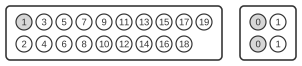
| Pin | Description |
|---|---|
| 1 | Red |
| 2 | Green |
| 3 | Blue |
| 4 | Monochrome / Overlay |
| 5 | Ground |
| 6 | Red Ground |
| 7 | Green Ground |
| 8 | Blue Ground |
| 9 | Audio Out |
| 10 | Ground |
| 11 | Ground |
| 12 | Composite Sync |
| 13 | Horizontal Sync |
| 14 | Vertikal Sync |
| 15 | External Clock Input |
| 16 | External Sync Enable |
| 17 | +12V for Scart |
| 18 | Videomode 1 |
| 19 | Videomode 2 |
Notes
The connector is a 19-pin Cannon (XLR-style circular) connector, male on the computer side. According to the Atari Falcon030 Service Guide (section 2.2.1.7), pin 9 carries Audio In (an audio signal input to the Falcon from an external source), not Audio Out as labelled in the original table — the pin table above is preserved byte-identical per policy, but note this correction. Pins 6, 7, and 8 are dedicated per-channel signal ground returns for Red, Green, and Blue respectively, rather than a shared ground, to minimise crosstalk on the analogue RGB lines. Pin 15 provides the GENLOCK external clock input, allowing the Falcon030 to synchronise its internal 32.215905 MHz (NTSC) or 32.084988 MHz (PAL) reference to an external video source. Pin 17 supplies +12V for PERITEL (SCART) adaptors. Pins 18 and 19 are the Video Master Control bits (M0 and M1) which select the active video mode. The Atari Falcon030 Owner’s Manual is known to have the top-row pin numbering reversed; always consult the Service Guide for authoritative pin assignments.
Settings
The videomode bits on pins 18 (M0) and 19 (M1) select the output mode:
| M0 | M1 | Monitor |
|---|---|---|
| 0 | 0 | mono |
| 0 | 1 | VGA |
| 1 | 0 | RGB |
| 1 | 1 | TV via CINCH |
Signals
- Red — Analogue red signal from the VIDEL 6-bit DAC (pin 1); dedicated ground return on pin 6.
- Green — Analogue green signal from the VIDEL 6-bit DAC (pin 2); dedicated ground return on pin 7.
- Blue — Analogue blue signal from the VIDEL 6-bit DAC (pin 3); dedicated ground return on pin 8.
- Monochrome / Overlay — Monochrome video output or overlay signal (pin 4), labelled “Mono Out” in the Service Guide.
- Ground — Signal ground references on pins 5, 10, and 11.
- Red Ground / Green Ground / Blue Ground — Per-channel analogue ground returns (pins 6, 7, 8) to minimise interference between colour channels.
- Audio In — Audio input to the Falcon030 from an external source (pin 9). Note: the original page labels this “Audio Out”, but the Service Guide section 2.2.1.7 explicitly identifies it as an input.
- Composite Sync — Combined horizontal and vertical sync signal (pin 12), used by RGB monitors.
- Horizontal Sync — Separate horizontal synchronisation signal (pin 13).
- Vertikal Sync — Separate vertical synchronisation signal (pin 14); note: “Vertikal” is the original spelling retained per table-freeze policy.
- External Clock Input — GENLOCK input (pin 15) for synchronising the Falcon030’s video output to an external video source.
- External Sync Enable — EVEN/ODD interlace signal (pin 16), referred to as “EVEN/ODD” in the Service Guide.
- +12V for Scart — Twelve-volt supply on pin 17 intended for PERITEL (SCART) adaptor circuits.
- Videomode 1 / Videomode 2 — Video Master Control bits M0 (pin 18) and M1 (pin 19) selecting mono, VGA, RGB, or TV output mode.