
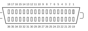
 36 pin MDR36 SGI female connector at the computer.
The Open LVDS Display Interface (OpenLDI), published by National Semiconductor as a draft specification (v0.95, May 1999), defines a logical, electrical, and mechanical interface between a display source and a flat-panel display device using LVDS signalling per ANSI/EIA/TIA-644. The connector is a 36-position, two-row shielded ribbon type with 0.050-inch contact spacing and a delta-shaped metal shell for shielding and polarity. The interface supports 18-bit and 24-bit colour in single-pixel and dual-pixel modes, with a minimum bit time of 893 ps corresponding to a maximum pixel clock of 160 MHz. SGI adopted this connector for its digital flat-panel monitors, and the interface is also known in the industry as M1. The VESA Display Information Extension Block standard (August 2001) assigns code 08h for OpenLDI single-link and 09h for OpenLDI dual-link in EDID extension blocks.
| Pin | Signal |
|---|---|
| 1 | Link2 D0- |
| 2 | Link2 DO+ |
| 3 | Link2 D1- |
| 4 | Link2 D1+ |
| 5 | Link2 D2- |
| 6 | Link2 D2+ |
| 7 | NC |
| 8 | NC |
| 9 | GND |
| 10 | GND |
| 11 | NC |
| 12 | NC |
| 13 | Link1 D0- |
| 14 | Link1 D0+ |
| 15 | Link1 D1- |
| 16 | Link1 D1+ |
| 17 | Link1 D2- |
| 18 | Link1 D2+ |
| 19 | Link2 D3- |
| 20 | Link2 D3+ |
| 21 | Link2 CLK- |
| 22 | Link2 CLK+ |
| 23 | DDD CLK SCL |
| 24 | VCC |
| 25 | GND |
| 26 | GND |
| 27 | NC |
| 28 | GND |
| 29 | NC |
| 30 | NC |
| 31 | NC |
| 32 | GND |
| 33 | Link1 CLK- |
| 34 | Link1 CLK+ |
| 35 | Link1 D3- |
| 36 | Link1 D3+ |
Signals
- Link1 D0–D3 — LVDS differential data pairs for the primary (single-pixel or first dual-pixel) channel; each pair carries serialised RGB pixel data.
- Link2 D0–D3 — LVDS differential data pairs for the secondary (second dual-pixel) channel; present in dual-pixel (dual-link) mode for higher resolutions or colour depths.
- Link1 CLK± / Link2 CLK± — LVDS differential clock pairs for Link 1 and Link 2 respectively; recovered at the display to deserialise pixel data.
- DDD CLK SCL — DDC clock / SCL line; used for Display Data Channel communication per VESA DDC/CI Standard v1 (August 1998), enabling plug-and-play via EDID.
- VCC — +5 V DC supply for DDC and ancillary logic.
- GND — Signal and power ground return.
- NC — Not connected; reserved positions in the 36-position shell.
Notes
- The OpenLDI v0.95 specification is the only publicly available revision; it was explicitly labelled subject to change before final publication and a ratified final version was never released publicly.
- LVDS signalling follows ANSI/EIA/TIA-644; differential amplitude template is ±900 mV peak with ±450 mV steady state, and intra-pair skew tolerance is 300 ps minimum.
- The 36-position delta-shaped metal shell provides 360-degree shielding and mechanical polarity; the connector cannot be inserted in the wrong orientation.
- Single-pixel mode uses Link 1 only; dual-pixel mode activates both Link 1 and Link 2, doubling pixel throughput for higher resolutions or refresh rates.
- The interface includes a USB 1.0 path (per USB Specification v1.0, January 1996) in the full OpenLDI specification, though not all implementations expose USB pins on the SGI variant of this connector.
- Hot-plug attach and removal events are supported via the DDC path and EDID plug-and-play mechanism.
- LVDS requires more signal pairs than TMDS for equivalent resolutions; the same pixel bandwidth that TMDS achieves with four channels (eight wires) can require up to twenty LVDS channels (forty wires), limiting practical cable length.
References
- Open LVDS Display Interface (OpenLDI) Specification v0.95 — National Semiconductor Corporation, May 1999
- VESA Display Information Extension Block Standard, Release A — Video Electronics Standards Association, August 2001