
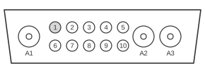
 13 PIN 13W3 FEMALE (At the Computer).
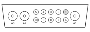 13 PIN 13W3 MALE (At the Cable).
Silicon Graphics workstations use the 13W3 (DB13W3) connector for analogue video output, a D-subminiature shell the width of a DB-25 carrying ten signal pins plus three large coaxial contacts (A1, A2, A3) for Red, Green, and Blue. Introduced in the early 1990s on the Personal IRIS and subsequent IRIX workstations, the connector supports typical resolutions of 1024×768 and 1280×1024 at refresh rates between 60 Hz and 76 Hz, with horizontal scan frequencies from 30 kHz to 82 kHz. SGI’s pin assignment differs from those of Sun, IBM, and NeXT, which use the identical physical shell but assign sync and identification bits quite differently; cross-vendor adapters are therefore non-trivial. There is no single ANSI/EIA standard mandating 13W3 pin assignments — each manufacturer chose its own wiring. SGI systems typically carry sync-on-green (composite H+V on the A2 coaxial contact) as well as a dedicated composite sync line (pin 3) and separate horizontal and vertical drive signals (pins 4 and 5); four Monitor-ID bits on pins 1, 2, 6, and 7 allow the graphics subsystem to detect the attached monitor and select the appropriate video timing at boot.
Normal Monitor
| Pin | Description |
|---|---|
| 1 | Monitor ID Bit 3, TTL |
| 2 | Monitor ID Bit 0, TTL |
| 3 | Composite Sync (Active Low), TTL |
| 4 | Horizontal Drive (Active High), TTL |
| 5 | Vertical Drive (Active High), TTL |
| 6 | Monitor ID Bit 1, TTL |
| 7 | Monitor ID Bit 2, TTL |
| 8 | Digital Ground |
| 9 | Digital Ground |
| 10 | Sync Ground |
DDC Monitor
| Pin | Description |
|---|---|
| 1 | Data Clock (SCL) |
| 2 | Bi-directional Data (SDA) |
| 3 | Composite Sync |
| 4 | Horizontal Sync |
| 5 | Vertical Sync |
| 6 | DDC (+5VInput) |
| 7 | DDC Ground |
| 8 | Chassis Ground |
| 9 | Chassis Ground |
| 10 | Chassis Ground |
| R | Red |
| G | Green |
| B | Blue |
Notes
- Signal type: analogue RGB; all RGB channels are carried on the A1, A2, and A3 coaxial contacts within the 13W3 shell.
- SGI supports multiple sync formats depending on the monitor and graphics subsystem: RsGsBs (sync-on-green on each channel), RGsB (composite H+V sync on Green only), RGBS (separate composite sync on pin 3), and RGBHV (separate H-drive and V-drive on pins 4 and 5, available with DDC-capable monitors).
- The Normal Monitor table uses non-sequential Monitor-ID bit ordering (pin 1 = bit 3, pin 2 = bit 0, pin 6 = bit 1, pin 7 = bit 2); this is correct per SGI hardware and matches the kev009.com cross-vendor comparison table.
- RGBHV mode (separate H and V sync on pins 4 and 5) is only available with DDC-equipped monitors; earlier SGI monitors expect composite sync (pin 3) or sync-on-green (A2 coaxial contact).
- The physical 13W3 shell is identical across SGI, Sun, IBM, and NeXT workstations; pin assignments are incompatible between vendors and require vendor-specific adapter cables.
- The SGI TG-V Graphics System Integrator’s Guide (document 007-5016-010, 1992) covers the video connector pinout for the Personal IRIS TG-V graphics subsystem, which uses this 13W3 arrangement.
Signals
- A1 (R) — Red analogue video, carried on a coaxial contact within the 13W3 shell.
- A2 (G) — Green analogue video coaxial contact; also carries composite H+V sync when operating in sync-on-green (RGsB or RsGsBs) mode.
- A3 (B) — Blue analogue video, carried on a coaxial contact within the 13W3 shell.
- Monitor ID Bit 0–3 — Four TTL identification bits (distributed non-sequentially across pins 1, 2, 6, 7) that encode the attached monitor type; the graphics subsystem reads these at boot to select default resolution and refresh timing.
- Composite Sync (Active Low) — Combined horizontal and vertical sync on a single TTL line (pin 3); used in RGBS mode.
- Horizontal Drive (Active High) — Separate horizontal sync signal (pin 4); used in RGBHV mode with DDC monitors.
- Vertical Drive (Active High) — Separate vertical sync signal (pin 5); used in RGBHV mode with DDC monitors.
- Digital Ground — Signal reference ground for TTL control lines (pins 8 and 9).
- Sync Ground — Dedicated ground return for the composite sync line (pin 10).
- Data Clock (SCL) — DDC clock line (pin 1 in DDC table); I²C-compatible SCL used for monitor identification in DDC mode.
- Bi-directional Data (SDA) — DDC data line (pin 2 in DDC table); I²C-compatible SDA used for EDID exchange in DDC mode.
- DDC (+5V Input) — 5 V supply provided to the monitor for DDC/EDID logic (pin 6 in DDC table).
References
- 13W3 Connector Pinout — IBM RS/6000 resource site (kev009.com)
- SGI TG-V Graphics System Integrator’s Guide, Document 007-5016-010, Silicon Graphics Inc., 1992 (archived at bitsavers.org: https://bitsavers.org/pdf/sgi/personal_iris/007-5016-010_TG-V_Graphics_System_Integrators_Guide_1992.pdf)