
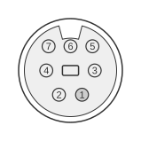
 7 PIN S-Video MINI-DIN Female
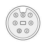 7 PIN S-Video MINI-DIN Male
The 7-pin mini-DIN S-Video connector is a proprietary extension of the standard 4-pin IEC 60933-5 S-Video socket, used on PC graphics cards from the late 1990s to the mid-2000s to carry S-Video, composite video, and optional control or digital audio signals through a single housing. Pins 1–4 are physically and electrically identical to the standard S-Video pinout (two grounds plus Y luminance and C chrominance), so a conventional 4-pin S-Video male plug fits mechanically into the 7-pin female receptacle. The assignment of the three extra pins varies between manufacturers: ATI used them for composite video and a composite video ground, whilst Dell’s variant (used on Inspiron, XPS, and Precision laptops) repurposed pin 5 for S/PDIF digital audio output and pin 7 for its corresponding ground. Because no single standard governs the additional pins, third-party adapter cables are required and are not interchangeable between vendors.
| Pin | Name | Description |
|---|---|---|
| 1 | GND | Ground (Y) |
| 2 | GND | Ground (C) |
| 3 | Y | Intensity (Luminance) |
| 4 | C | Color (Chrominance) |
| 5 | - | - |
| 6 | V | Composite Video |
| 7 | VGND | Composite Ground |
Notes
- This is a proprietary, non-standardised connector. There is no governing body specification for the 7-pin variant; the extra pins are vendor-defined.
- Pins 1–4 universally follow the standard IEC 60933-5 S-Video assignment (GND-Y, GND-C, Y, C). A standard 4-pin S-Video male plug fits the 7-pin female receptacle mechanically and carries S-Video signals correctly on those four pins.
- The assignment of pins 5–7 varies by manufacturer. ATI graphics cards used pin 6 for composite video (CVBS) and pin 7 for composite ground; pin 5 was left unassigned or used for a control signal. Dell laptops (Inspiron 8200, XPS M1710/M1730, Precision M90, and related models) used pin 5 for S/PDIF coaxial digital audio and pin 7 for S/PDIF ground, with pin 6 carrying composite video — S/PDIF output is only active when pin 5 is shorted to ground by the adapter cable.
- Vendor-specific adapter cables are required to split the 7-pin connector into individual S-Video, composite RCA, and (on Dell) S/PDIF outputs. Cables are not interchangeable across vendors even though the housings are mechanically identical.
- S-Video signal levels follow the IEC 60933-5 specification: Y (luminance) at approximately 1 V peak-to-peak into 75 Ω, C (chrominance) at approximately 0.3 V peak-to-peak into 75 Ω.
Signals
- GND (Y) — Signal ground reference for the Y luminance line (pin 1, per IEC 60933-5 S-Video standard).
- GND (C) — Signal ground reference for the C chrominance line (pin 2, per IEC 60933-5 S-Video standard).
- Y — Luminance (intensity) component of the S-Video signal; carries black-and-white picture information.
- C — Chrominance (colour) component of the S-Video signal; carries colour information encoded as a phase-modulated subcarrier.
- Pin 5 — Vendor-defined; unassigned on many ATI implementations. On Dell laptop variants, carries S/PDIF coaxial digital audio output (active only when shorted to ground by the adapter).
- V — Composite video (CVBS) output, 1 V peak-to-peak into 75 Ω. Simultaneously active alongside S-Video on ATI and Dell implementations.
- VGND — Ground reference for the composite video line (pin 7). On Dell variants this pin serves as the S/PDIF ground.
References
- Dell Inspiron 8200 Service Manual — Dell Inc.; official pin table for the 7-pin S-Video TV-Out connector on pages 87–88, including S/PDIF and composite assignments.