
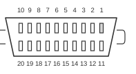
 20 pin MDR20 female connector
The VESA Digital Flat Panel (DFP) standard, ratified on 14 February 1999, defines a 20-pin Mini D Ribbon (MDR-20) connector for carrying single-link TMDS (Transition Minimised Differential Signalling) digital video directly to flat-panel displays. Like the later DVI standard, it uses Silicon Image’s PanelLink TMDS protocol with four differential channel pairs (three data, one clock), supporting a maximum pixel clock of 165 MHz, but it is strictly digital — there is no provision for analogue video, USB, or FireWire. The VESA DI-EXT standard (August 2001) assigns interface code 07h to DFP in EDID extension blocks, and DVI implementations are explicitly designed to connect to DFP equipment through a simple passive adapter.
| Pin | Signal |
|---|---|
| 1 | TMDS Data 1 + |
| 2 | TMDS Data 1 |
| 3 | Ground |
| 4 | Ground |
| 5 | TMDS Data C + |
| 6 | TMDS Data C |
| 7 | Ground |
| 8 | +5V |
| 9 | Reserved |
| 10 | Reserved |
| 11 | TMDS Data 2 + |
| 12 | TMDS Data 2 - |
| 13 | Ground |
| 14 | Ground |
| 15 | TMDS Data 0 + |
| 16 | TMDS Data 0 - |
| 17 | Reserved |
| 18 | Reserved |
| 19 | DDC Data |
| 20 | DDC Clock |
Notes
- The MDR-20 connector is keyed to prevent incorrect insertion; the host must supply +5 V on pin 8 as mandated by the DFP standard.
- DFP supports only single-link TMDS; maximum pixel clock is 165 MHz, covering resolutions up to QXGA (2048×1536).
- Mandatory minimum resolutions are 640×400, 720×400, and 640×480 at 60 Hz.
- DVI equipment connects to DFP via a simple passive mechanical adapter; however, adapters must leave the Hot Plug Detect line disconnected or clamped to +5 V, since the P&D-family HPD pin may carry up to +20 V whereas DVI HPD is +5 V.
- The VESA DI-EXT standard (August 2001) assigns digital interface code 07h to DFP in EDID extension blocks.
Signals
- TMDS Data 0± — TMDS differential data pair 0 (channel 0)
- TMDS Data 1± — TMDS differential data pair 1 (channel 1)
- TMDS Data 2± — TMDS differential data pair 2 (channel 2); labelled “Data C” in some sources
- TMDS Data C± — TMDS clock differential pair; carries the pixel clock for all three data channels
- DDC Data — Display Data Channel (DDC2B) serial data line; used for EDID plug-and-play communication
- DDC Clock — DDC2B serial clock line
- +5V — Host-supplied +5 V DC power (pin 8); mandatory per VESA DFP standard
- Ground — Signal and power return
- Reserved — Pins 9, 10, 17, and 18 are reserved and must not be connected