
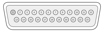
 23 PIN D-SUB MALE at the Amiga.
All Amiga models (A500, A1000, A2000, A3000, A4000) carry a 23-pin D-Sub male video connector on the rear panel, defined in Appendix E of the Amiga Hardware Reference Manual (3rd ed., Commodore-Amiga Inc./Addison-Wesley, 1991). The connector provides simultaneous analogue RGB output (75 ohm, pins 3–5), digital RGB intensity signals (47 ohm, pins 6–9), composite/horizontal/vertical sync, and a full set of genlock interface signals — all on a single cable. Sync outputs (CSYNC, HSYNC, VSYNC*) are unbuffered at the source; external line buffers are required when driving heavy capacitive loads such as distribution amplifiers or multiple monitors.
| Pin | Name | Dir | Description |
|---|---|---|---|
| 1 | /XCLK | IN | Extern Clock |
| 2 | /XCLKEN | IN | Extern Clock Enable (47 Ohm) |
| 3 | RED | OUT | Analog Red (75 Ohm) |
| 4 | GREEN | OUT | Analog Green (75 Ohm) |
| 5 | BLUE | OUT | Analog Blue (75 Ohm) |
| 6 | DI | OUT | Digital Intensity (47 Ohm) |
| 7 | DB | OUT | Digital Blue (47 Ohm) |
| 8 | DG | OUT | Digital Green (47 Ohm) |
| 9 | DR | OUT | Digital Red (47 Ohm) |
| 10 | /CSYNC | OUT | Composite Sync (47 Ohm) |
| 11 | /HSYNC | OUT | Horizontal Sync (47 Ohm) |
| 12 | /VSYNC | OUT | Vertical Sync (47 Ohm) |
| 13 | GNDRTN | - | Digital Ground (for /XCLKEN) Don’t connect with pin 16-20. |
| 14 | /ZD | OUT | Genlock overlay (47 Ohm) |
| 15 | /C1 | OUT | Clock out (47 Ohm) |
| 16 | GND | - | Video Ground |
| 17 | GND | - | Video Ground |
| 18 | GND | - | Video Ground |
| 19 | GND | - | Video Ground |
| 20 | GND | - | Video Ground |
| 21 | -12V -5V | OUT | -12 Volts DC (10 mA max) (A500/A600/A1200) -5 Volts DC (10 mA max) (A1000/A2000/A3000/A4000) |
| 22 | +12V | OUT | +12 Volts DC (100 mA max) |
| 23 | +5V | OUT | +5 Volts DC (100 mA max) |
Notes
- Direction is Computer relative Monitor
- Pin 21 carries a negative supply whose voltage varies by model: −12 V on the A500, A600, and A1200; −5 V on the A1000, A2000, A3000, and A4000. Using a cable made for one group on the other is a common source of compatibility errors.
- GNDRTN (pin 13) is a dedicated return path for the /XCLKEN signal and must not be connected to the main video grounds on pins 16–20.
- All sync outputs (pins 10–12) are unbuffered; add an external buffer before connecting to multiple devices or long cable runs.
Signals
- XCLK* — external clock input from a genlock device; drives the Amiga pixel clock to synchronise with an incoming video source
- XCLKEN* — external clock enable; active-low, 47 ohm; gates the genlock clock onto the internal pixel clock bus
- RED / GREEN / BLUE — analogue RGB video outputs, 75 ohm; standard composite-sync-on-green is not provided; sync is on dedicated pins
- DI — digital intensity bit (47 ohm); combined with DB/DG/DR to form a 4-bit RGBI signal compatible with TTL colour monitors
- DB / DG / DR — digital blue, green, and red outputs (47 ohm each); together with DI these drive the digital RGBI interface
- CSYNC* — composite sync output (47 ohm); H and V sync combined; used by monitors that accept composite sync on a single line
- HSYNC* — horizontal sync output (47 ohm); unbuffered
- VSYNC* — vertical sync output (47 ohm); unbuffered
- GNDRTN — dedicated ground return for /XCLKEN only; must not be connected to pins 16–20
- ZD* — Zero Detect; active-low genlock signal (47 ohm); pulses when the current pixel value is zero (black), allowing genlock hardware to determine when to overlay external video. Also referred to as /PIXELSW in some A4000-era documentation, but ZD* is the authoritative name given in the Amiga HRM Appendix E for all earlier models
- C1* — 3.58 MHz colour clock output (47 ohm); provided for genlock and external video synchronisation
- GND (pins 16–20) — five video ground pins; keep isolated from GNDRTN on pin 13
- −12 V / −5 V (pin 21) — negative supply rail; see Notes above for model-dependent voltage
- +12 V (pin 22) — +12 V supply, 100 mA maximum
- +5 V (pin 23) — +5 V supply, 100 mA maximum
References
- Amiga Hardware Reference Manual, 3rd Edition, Commodore-Amiga Inc./Addison-Wesley, 1991, ISBN 0-201-56776-8 (archive.org: https://archive.org/details/amiga-hardware-reference-manual-3rd-edition)