
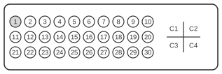
 35 pin MOLEX “MicroCross” female connector at the videocard and monitor.
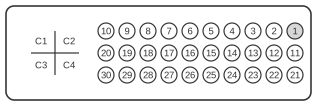 35 pin MOLEX “MicroCross” male connector at the video cable.
The VESA Enhanced Video Connector (EVC), ratified November 1994, and its successor VESA Plug & Display (P&D), standardised on 11 June 1997, share the same 30-pin-plus-quad-coax physical layout on a 35-position MOLEX MicroCross shell. The two variants are distinguished by shell geometry: EVC uses an isosceles-trapezoid shell, whilst P&D uses a D-shaped shell. P&D defines two sub-types — P&D-D (digital only) and P&D-A/D (analogue and digital) — both carrying Silicon Image TMDS digital video alongside optional analogue RGB, USB, and IEEE 1394 (FireWire) on a single cable. The standard was superseded by DVI, which is explicitly designed for backward compatibility with P&D via passive adapters.
| Pin | Signal |
|---|---|
| 1 | TMDS Data 2 + |
| 2 | TMDS Data 2 |
| 3 | Ground |
| 4 | Ground |
| 5 | Hsync |
| 6 | Vsync |
| 7 | Ground |
| 8 | CP+ |
| 9 | 1394 Pair Data 1 A |
| 10 | 1394 Pair Data 1 A + |
| 11 | TMDS Data 1 + |
| 12 | TMDS Data 1 |
| 13 | Ground |
| 14 | TMDS Clock + |
| 15 | TMDS Clock |
| 16 | USB Data + |
| 17 | USB Data |
| 18 | Ground / 1394 SHIELD / CHARGING POWER INPUT- |
| 19 | 1394 VG |
| 20 | 1394 VP |
| 21 | TMDS Data 0 + |
| 22 | TMDS Data 0 |
| 23 | Ground |
| 24 | Stereo Sync |
| 25 | Ground |
| 26 | DDC Data |
| 27 | DDC Clock |
| 28 | +5VDC |
| 29 | 1394 Pair Data 1 B |
| 30 | 1394 Pair Data 1 B + |
| C1 | RED VIDEO OUT |
| C2 | GRN VIDEO OUT |
| C3 | PX CLOCK OUT |
| C4 | BLU VIDEO OUT |
| C5 | COMMON GND RTN |
Notes
- The EVC (isosceles-trapezoid shell) and P&D (D-shaped shell) share the identical 30-pin + 4-coax contact layout; they are mechanically incompatible despite identical electrical pinouts.
- P&D-D carries digital-only TMDS; P&D-A/D additionally routes analogue RGB on the four coaxial positions (C1–C4), with C5 as common return.
- TMDS signalling follows Silicon Image PanelLink: four differential pairs per link (three data, one clock); 8b/10b DC-balanced encoding; single-link maximum pixel clock 165 MHz.
- The Hot Plug Detect (HPD) pin on P&D may carry up to +20 V. DVI HPD is +5 V; any adapter between P&D and DVI must leave HPD unconnected or clamp it to 5 V.
- DDC is carried on pins 26–27; VESA DDC and EDID 2.0 are referenced by the P&D standard for plug-and-play display identification.
- USB (pins 16–17) and IEEE 1394 FireWire (pins 9–10, 29–30, 19–20) are optional features of the P&D standard; not all implementations populate them.
- The VESA DI-EXT standard (August 2001) assigns EDID extension code 06h to P&D connectors.
Signals
- TMDS Data 0/1/2 ± — TMDS differential data pairs carrying encoded digital video; three pairs per single link using Silicon Image PanelLink 8b/10b encoding
- TMDS Clock ± — differential clock reference for the TMDS data pairs; single-link maximum 165 MHz pixel clock
- Hsync — horizontal synchronisation signal for analogue video timing
- Vsync — vertical synchronisation signal for analogue video timing
- Stereo Sync — synchronisation signal for active-shutter stereo (3D) display equipment
- CP+ — copy protection / content protection signal
- USB Data ± — USB 1.x differential data pair for optional downstream USB connectivity
- 1394 Pair Data 1 A / A+ — IEEE 1394 (FireWire) differential data pair A (strobe or data)
- 1394 Pair Data 1 B / B+ — IEEE 1394 (FireWire) differential data pair B (strobe or data)
- 1394 VG — IEEE 1394 ground reference
- 1394 VP — IEEE 1394 power supply rail
- DDC Data — I²C data line for VESA DDC display data channel (EDID communication)
- DDC Clock — I²C clock line for VESA DDC display data channel
- +5VDC — 5 V power supply to the display for DDC and identification circuitry
- Ground / 1394 SHIELD / CHARGING POWER INPUT- — combined ground, IEEE 1394 shield, and charging power return
- Ground — signal and power ground references (multiple pins)
- RED VIDEO OUT (C1) — analogue red component video output (P&D-A/D only)
- GRN VIDEO OUT (C2) — analogue green component video output (P&D-A/D only)
- PX CLOCK OUT (C3) — analogue pixel clock output (P&D-A/D only)
- BLU VIDEO OUT (C4) — analogue blue component video output (P&D-A/D only)
- COMMON GND RTN (C5) — common coaxial ground return for analogue signals