
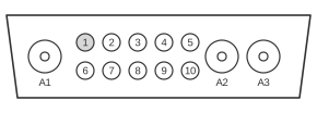
 13 PIN 13W3 FEMALE (At the Computer).
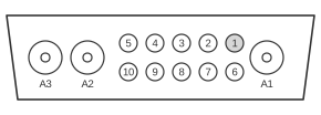 13 PIN 13W3 MALE (At the Cable).
Certain IBM PowerPC and RS/6000 workstations — including models fitted with the GXT150M graphics adapter — use the 13W3 (DB13W3) video connector, a D-subminiature shell the width of a DB-25 that carries ten signal pins alongside three large coaxial contacts (A1/A2/A3) for the Red, Green, and Blue analogue video channels. Unlike SGI and Sun systems that share the same physical shell, IBM’s implementation routes separate horizontal and vertical sync signals to dedicated pins rather than using sync-on-green or composite sync. There is no single ANSI/EIA standard governing 13W3 pin assignments; each manufacturer chose its own wiring, making cross-vendor adapters non-trivial despite identical physical connectors. The IBM variant supports resolutions from 640×480 to 1600×1200, with horizontal scan rates of 31–61 kHz and vertical rates of 60–87 Hz.
| Pin | Description |
|---|---|
| 1 | ID Bit 2 |
| 2 | ID Bit 3 |
| 3 | Self test |
| 4 | Digital Ground |
| 5 | Horizontal Sync |
| 6 | ID Bit 0 |
| 7 | ID Bit 1 |
| 8 | n/c |
| 9 | Vertical Sync |
| 10 | Digital Ground |
| R | Red/R-Gnd |
| G | Green/G-Gnd |
| B | Blue/B-Gnd |
Signals
- R (A1) — Red analogue video, carried on a coaxial contact with its own shield/ground.
- G (A2) — Green analogue video, carried on a coaxial contact. IBM does not carry sync on this line (unlike SGI’s sync-on-green approach).
- B (A3) — Blue analogue video, carried on a coaxial contact.
- ID Bit 0 / ID Bit 1 / ID Bit 2 / ID Bit 3 — Monitor identification bits (pins 6, 7, 1, 2 respectively). These four lines allow the graphics adapter to identify the attached monitor model and select appropriate timing defaults.
- Self test — IBM-specific signal on pin 3, used for adapter self-test. On SGI systems this pin carries composite sync; on Sun systems composite sync is on pin 5 — making this the clearest source of cross-vendor incompatibility.
- Horizontal Sync — Separate TTL-level HSYNC on pin 5 (positive or negative polarity depending on mode).
- Vertical Sync — Separate TTL-level VSYNC on pin 9.
- Digital Ground — Logic-level ground on pins 4 and 10, distinct from the coaxial shield grounds on the RGB contacts.
- n/c — Pin 8 is not connected on IBM RS/6000 implementations.
Notes
- The 13W3 shell is mechanically identical across IBM, SGI, Sun, and NeXT systems, but pin assignments are incompatible — connecting a Sun or SGI cable to an IBM port risks damage.
- A standard 13W3-to-HD15 (VGA) adapter wires: A1 → HD15 pin 1 (Red), A2 → pin 2 (Green), A3 → pin 3 (Blue), pin 5 (HSYNC) → HD15 pin 13, pin 9 (VSYNC) → HD15 pin 14.
- Not all IBM PowerPC models used 13W3; later and entry-level machines fitted a standard HD-15 VGA output instead.
- IBM monitor models confirmed to use this connector include the 6091-019, 6312, 6314, and the 6315–6327 series.