
The IBM PCjr (1983) provides CGA-compatible colour video through three separate outputs on the system board: an 18-pin dual-row Berg-style header for direct-drive RGBI displays, an RCA jack for composite video, and a 6-pin header for the optional RF modulator (television). The direct-drive header carries 4-bit RGBI signals at standard TTL levels, enabling 16 colours in palette mode and 2, 4, or 16 colours in graphics modes. Unlike the IBM PC CGA card, which uses a 9-pin DE-9 socket, the PCjr routes its video through this proprietary dual-row connector on the motherboard, with the Video Gate Array LSI5220 and a Motorola 6845 CRT controller driving the video subsystem.
18 Pin BERG STYLE CONNECTOR
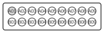
| Pin | Description |
|---|---|
| A01 | TV vertical drive (not for display) |
| A02 | Ground |
| A03 | TV horizontal drive (not for display) |
| A04 | Blue (CGA pin 5) |
| A05 | Red (CGA pin3) |
| A06 | Intensity (CGA pin 6) |
| A07 | Green (CGA pin 4) |
| A08 | Comp Sync Drive (not for display) |
| A09 | Audio |
| B01 | + Vertical drive (CGA pin 9) |
| B02 | Ground |
| B03 | + Horizontal drive (CGA pin 8) |
| B04 | Ground |
| B05 | Ground |
| B06 | Ground |
| B07 | Ground |
| B08 | Ground |
| B09 | Frame ground (CGA pin 1) |
Signals
- A01 — TV Vertical Drive — vertical sync signal routed to the RF modulator; not used for direct-drive RGBI displays.
- A02 — Ground — signal ground.
- A03 — TV Horizontal Drive — horizontal sync signal routed to the RF modulator; not used for direct-drive RGBI displays.
- A04 — Blue — TTL blue colour signal (corresponds to CGA DE-9 pin 5, bit 0 of the 4-bit RGBI encoding).
- A05 — Red — TTL red colour signal (corresponds to CGA DE-9 pin 3, bit 2 of the 4-bit RGBI encoding).
- A06 — Intensity — TTL intensity bit (corresponds to CGA DE-9 pin 6, bit 3); when asserted, brightens all active colour channels to produce the upper 8 of the 16-colour palette.
- A07 — Green — TTL green colour signal (corresponds to CGA DE-9 pin 4, bit 1 of the 4-bit RGBI encoding).
- A08 — Composite Sync Drive — composite sync signal routed to the RF modulator output; not used for direct-drive RGBI displays.
- A09 — Audio — analogue audio output, 1 V peak-to-peak biased at 0 V, for loads of 10 kohm or greater impedance.
- B01 — +Vertical Drive — positive vertical sync (corresponds to CGA DE-9 pin 9); used by direct-drive RGBI monitors.
- B02 — Ground — signal ground.
- B03 — +Horizontal Drive — positive horizontal sync (corresponds to CGA DE-9 pin 8); used by direct-drive RGBI monitors.
- B04–B08 — Ground — signal grounds.
- B09 — Frame Ground — chassis/frame ground (corresponds to CGA DE-9 pin 1).
Notes
- The connector is an 18-pin dual-row Berg-style header (9 pins in row A, 9 pins in row B), not the DE-9 used on the IBM PC CGA card. The PCjr system board labels this connector D (Direct Drive Video).
- All RGBI and sync signals operate at standard TTL levels.
- The composite video RCA jack on the system board (connector V) outputs 1 V peak-to-peak biased at 0.7 V with a 75-ohm load.
- The RF modulator connector (connector T, 6-pin header) carries: A01 = +12 V, A02 = Key, A03 = Composite Video, B01 = GND, B02 = Audio, B03 = Shield GND.
- The PCjr’s 4-bit RGBI colour encoding is compatible with the IBM CGA standard: Bit 0 = Blue, Bit 1 = Green, Bit 2 = Red, Bit 3 = Intensity.
References
- IBM PCjr Technical Reference (November 1983) — IBM Corporation (via Bitsavers / Internet Archive)