
- VGA = Video Graphics Adapter or Video Graphics Array
- VESA = Video Electronics Standards Association
- DDC = Display Data Channel
Videotype: Analogue.
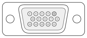 15 PIN HIGHDENSITY D-SUB FEMALE at the videocard
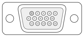 15 PIN HIGHDENSITY D-SUB MALE at the monitor cable
The VGA connector is a 15-pin high-density D-subminiature (HD-15, also known as DE-15) introduced by IBM in 1987 with the PS/2 family, carrying analogue RGB video signals (0–0.7 V, 75 Ω) alongside TTL-level horizontal and vertical sync. VESA’s Display Data Channel (DDC) standard, first published in August 1994, added plug-and-play capability by repurposing the legacy Monitor ID pins: pin 12 became the I2C serial data line (SDA) and pin 15 the serial clock (SCL), enabling the host to read EDID identification data from the display’s EEPROM. The later VESA Enhanced DDC 1.2 standard (December 2007) further defined pin 9 as a +5 V supply (minimum 50 mA) to power DDC electronics in the monitor even when the display is not connected to mains, and extended the addressable EDID space to 32 KB via a segment pointer at I2C address 60h.
| Pin | Name | Dir | Description |
|---|---|---|---|
| 1 | RED | OUT | Red Video (75 ohm, 0.7 V p-p) |
| 2 | GREEN | OUT | Green Video (75 ohm, 0.7 V p-p) |
| 3 | BLUE | OUT | Blue Video (75 ohm, 0.7 V p-p) |
| 4 | RES | - | Reserved |
| 5 | GND | —— | Ground |
| 6 | RGND | —— | Red Ground |
| 7 | GGND | —— | Green Ground |
| 8 | BGND | —— | Blue Ground |
| 9 | +5V | OUT | +5 VDC |
| 10 | SGND | —— | Sync Ground |
| 11 | ID0 | IN | Monitor ID Bit 0 (optional) |
| 12 | SDA | IN/OUT | DDC Serial Data Line |
| 13 | HSYNC or CSYNC | OUT | Horizontal Sync (or Composite Sync) |
| 14 | VSYNC | OUT | Vertical Sync |
| 15 | SCL | IN/OUT | DDC Data Clock Line |
Notes
- Direction is Computer relative to Monitor.
- Pin 9 was a mechanical key (missing pin) on the original IBM VGA connector; DDC-capable hosts recess the pin 9 socket by 0.050 inches and use royal-blue plastic to indicate DDC compatibility, per VESA E-DDC 1.2. The host must supply +5 V ±5% at a minimum of 50 mA with overcurrent protection to a maximum of 1 A; the display may draw up to 50 mA when not AC powered.
- Pin 4 carried Monitor ID bit 2 in the pre-DDC IBM VGA definition; it is reserved (no connection) in the DDC/E-DDC pinout.
- Pin 11 carried Monitor ID bit 0 in the legacy IBM VGA definition; in the DDC display side it is reserved (no connection), though some hosts still implement it as an optional identification bit.
- The IBM Video Subsystem Technical Reference specifies that VSYNC polarity encodes the active display mode: −/+ = 350 lines, +/− = 400 lines, −/− = 480 lines, +/+ = other.
- There are three DDC protocol variants defined by VESA for this connector:
- DDC1 — A unidirectional (display to host only) serial communication system providing basic display identification and feature information (supported timings, display size, colorimetry, gamma, etc.) to the host. Uses pin 12 as a data line, clocked by VSYNC on pin 14.
- DDC2B — Adds a dedicated clock on pin 15 (SCL) to enable bidirectional I2C communication; EDID data is read at I2C addresses A0h/A1h. Display control via DDC2B is not defined.
- DDC2AB — Full identification and control of the monitor via ACCESS.bus. As ACCESS.bus is a command and protocol layer on top of the I2C hardware interface, it uses the same lines as DDC2B.
- VESA Enhanced DDC (E-DDC 1.2) extends DDC2B by adding a segment pointer at I2C address 60h, enabling display data structures up to 32 KB. The base EDID block remains 128 bytes at address A0h, as defined by the VESA E-EDID standard (Release A, Revision 2, September 2006).
Signals
- RED — Analogue red video, 0 to 0.7 V peak-to-peak, 75 Ω terminated.
- GREEN — Analogue green video, 0 to 0.7 V peak-to-peak, 75 Ω terminated. Some hosts support sync-on-green (SOG) on this pin when agreed by both sides.
- BLUE — Analogue blue video, 0 to 0.7 V peak-to-peak, 75 Ω terminated.
- RES — Reserved; carries no signal in the DDC/E-DDC pinout (was Monitor ID bit 2 in legacy IBM VGA).
- GND — Signal ground.
- RGND — Return ground for the red video coaxial pair.
- GGND — Return ground for the green video coaxial pair.
- BGND — Return ground for the blue video coaxial pair.
- +5V — DDC +5 V supply from host to display (pin 9); must be +5 V ±5%, minimum 50 mA. Was a mechanical key (absent pin) on the original IBM VGA.
- SGND — Sync signal ground.
- ID0 — Legacy Monitor ID bit 0; reserved (no connection) on the DDC display side.
- SDA — I2C serial data line for DDC/E-DDC; bidirectional, open-drain. Carries EDID data from the display EEPROM.
- HSYNC or CSYNC — Horizontal sync (TTL level) or composite sync. Polarity and timing define the active video mode.
- VSYNC — Vertical sync (TTL level). Polarity encodes display mode in the IBM VGA specification.
- SCL — I2C serial clock for DDC2B/E-DDC (pin 15); driven by the host. Was Monitor ID bit 3 in the legacy IBM VGA definition.