
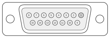
 15 pin D-SUB female connector at the computer.
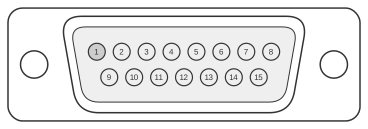 15 pin D-SUB male connector at the video cable.
The Macintosh II Video Card (NuBus, 1987) and its successors used a DA-15 female connector — a two-row, 15-pin D-type shell, colloquially but incorrectly called DB-15 — to carry separate analogue RGB signals, composite sync, and independent horizontal and vertical sync to Apple-manufactured monitors. Three monitor-sense lines (SENSE0 on pin 4, SENSE1 on pin 7, SENSE2 on pin 10), read against monitor ground on pin 11, form a 3-bit code that the system uses to identify the connected display type, as defined in Apple Technical Note HW30 (September 1992). The same DA-15 pinout was shared across the High-Resolution Video Card, Extended High-Resolution Video Card, and the Display Card 4•8, 8•24, and 8•24 GC family; VRAM fitted to the card determined colour depth (256 KB for 4-bit/16 colours, 512 KB for 8-bit/256 colours at 640×480). Early versions of the Macintosh II Video Card lacked the SENSE0/1/2 pullup resistors; later revisions and the IIci built-in video added them, requiring pin 4 to be grounded by the monitor or cable for correct 640×480 detection.
| Pin | Name | Description |
|---|---|---|
| 1 | RED.GND | Red ground |
| 2 | RED.VID | Red video signal |
| 3 | /CSYNC | Composite synchronization signal |
| 4 | MON.ID1 | Monitor ID bit 1 |
| 5 | GRN.VID | Green video signal |
| 6 | GRN.GND | Green ground |
| 7 | MON.ID2 | Monitor ID bit 2 |
| 8 | n/c | Not connected |
| 9 | BLU.VID | Blue video signal |
| 10 | MON.ID3 | Monitor ID bit 3 |
| 11 | C&VSYNC.GND | Ground for CSYNC & VSYNC |
| 12 | /VSYNC | Vertical synchronization signal |
| 13 | BLU.GND | Blue ground |
| 14 | HSYNC.GND | HSYNC ground |
| 15 | /HSYNC | Horizontal synchronization signal |
| Shell | CHASSIS.GND | Chassis ground |
Signals
- RED.VID / GRN.VID / BLU.VID — Analogue red, green, and blue video signals (pins 2, 5, 9); each paired with its own dedicated ground return (pins 1, 6, 13).
- /CSYNC — Active-low composite synchronisation signal combining horizontal and vertical sync; its ground return is pin 11.
- /HSYNC — Active-low horizontal synchronisation signal; ground return is pin 14.
- /VSYNC — Active-low vertical synchronisation signal; ground return is pin 11.
- MON.ID1 / MON.ID2 / MON.ID3 — Monitor sense lines SENSE0, SENSE1, and SENSE2 respectively (pins 4, 7, 10). Each line is either grounded by the monitor (binary 0) or left floating (binary 1), forming a 3-bit code read against pin 11 to identify the display type. When all three read high (111), the Extended Type-7 dynamic polling protocol is triggered to yield a 6-bit identification code. The governing specification is Apple Technical Note HW30.
- n/c — Pin 8 is not connected.
- CHASSIS.GND — Shell/chassis ground.
Notes
- The connector is correctly designated DA-15 (two rows of pins in a D-type shell); the three-row DB-15 designation widely used in third-party documentation is technically incorrect, though the physical connector is sometimes mislabelled in this way.
- On early Macintosh II Video Cards, pins 7 and 10 lacked pullup resistors; grounding pin 4 (SENSE0) in the cable was therefore necessary for the card to recognise a 640×480 monitor. Later card revisions and the IIci built-in video added the pullup resistors.
- The DA-15 signals on Macintosh video cards are electrically and logically incompatible with the DA-15/DB-15 connectors on the Apple IIc, Apple IIGS, Apple III, and EtherTalk Interface Card — do not cross-connect.
- Standard monitor type codes (3-bit sense values) are tabulated in Guide to the Macintosh Family Hardware (2nd ed., 1990), Table 12-2, and in Apple Technical Note HW30.
References
- Guide to the Macintosh Family Hardware, Second Edition (1990) — Apple Computer, Inc. / Addison-Wesley; Chapter 12 Tables 12-1 and 12-2 cover the DA-15 pin assignments and monitor sense codes.
- Apple Technical Note HW30: Sense Lines (September 1, 1992) — Apple Computer, Inc.; governing specification for the 3-bit and extended 6-bit monitor-identification scheme.
- Apple Technical Note HW08: Color Monitor Connections (February 1, 1991) — Apple Computer, Inc.; adapter cable wiring for connecting Macintosh II Video Card output to third-party monitors.
- Apple Ports and Pinouts (Service Source K reference) — Apple Computer, Inc. (archived); DA-15 male pin assignments and caution note regarding incompatible DA-15 connectors on non-Macintosh Apple hardware.