
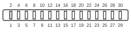
30 PIN CONNECTOR at the computer.
The CDTV video slot is a 30-pin internal edge connector used to connect swappable video output modules to Commodore’s CDTV multimedia player, introduced in 1991. The CDTV is architecturally an Amiga 500 with an integrated CD-ROM drive, and the video slot carries the same analogue and digital video signals found on the standard Amiga DB-23 external connector, routed internally to whichever output module is fitted (typically the RF modulator). The slot supports three operating modes: CDTV as the sole video source, an external video source, or a mixed genlock mode in which an external signal is overlaid. Video outputs available externally include analogue RGB and digital RGB via a DB-23, composite NTSC/PAL via RCA jacks, Y-C (S-Video), and RF via F-connector; graphics modes span 320×200 non-interlaced up to 640×400 interlaced (NTSC) or up to 512 lines (PAL).
| Pin | Name | Description |
|---|---|---|
| 1 | GND | Video Ground |
| 2 | GND | Video Ground |
| 3 | XCLK | External Genlock Clock (in) |
| 4 | R | Red (in to video card) |
| 5 | /XCLKEN | Enables External Clock on XCLK. |
| 6 | BR | Buffered Red (out from video card) |
| 7 | GND | Video Ground |
| 8 | G | Green (in to video card) |
| 9 | GMS0 | Genlock mode 0 (from computer, genlock button) |
| 10 | BG | Buffered Green (out from video card) |
| 11 | GMS1 | Genlock mode 1 (from computer, genlock button) |
| 12 | B | Blue (in to video card) |
| 13 | /PIXELSW | Genlock signal |
| 14 | BB | Buffered Blue (out from video card) |
| 15 | VSYNC | Vertical Sync (in to video card) |
| 16 | CSYNC | Horizontal Sync (in to video card) |
| 17 | HSYNC | Composite Sync (in to video card) |
| 18 | BCSYNC | Buffered Composite Sync (out from video card) |
| 19 | GND | Video Ground |
| 20 | AUDR | Audio Right Output (from computer to RF modulator) |
| 21 | DGND | Digital Ground |
| 22 | AUDL | Audio Left Output (from computer to RF modulator) |
| 23 | -12V | -12 VDC (can be -5 VDC instead) |
| 24 | DGND | Digital Ground |
| 25 | +12V | +12 VDC |
| 26 | /CD/TV | CD/TV button. (Low=CDTV video on RF, High=Antenna) |
| 27 | VCC | +5 VDC |
| 28 | /CCK | 3.58 MHz color clock (C1 clock) |
| 29 | GND | Video Ground |
| 30 | VCC | +5 VDC |
Notes
- The slot is primarily occupied by the RF modulator module in standard CDTV units; alternative modules (SCART, genlock, DCTV) use the same connector.
- The CDTV shares the Amiga 500’s −12V rail; pin 23 carries −12 VDC. Some third-party video modules for other Amiga models used −5 VDC on the equivalent pin — these are not interchangeable without hardware modification.
- GMS0 (pin 9) and GMS1 (pin 11) are set by the genlock button and select among the three video modes: CDTV-only, external-only, or mixed overlay.
- /CCK (pin 28) is the 3.58 MHz colour burst clock (equivalent to the Amiga’s C1 clock), required by NTSC RF and composite video generation circuitry.
- The pin 16/17 labels follow the CDTV Service Manual convention: CSYNC carries composite sync and HSYNC carries horizontal sync — note this is the reverse of the naming used in some Amiga documentation.
Signals
- GND — Video signal ground (pins 1, 2, 7, 19, 29); kept separate from digital ground pins.
- XCLK — External genlock clock input; accepts an incoming video reference clock from an external source for synchronisation.
- R / G / B — Unbuffered analogue red, green, and blue video signals from the Amiga chipset (input to the video module).
- /XCLKEN — Active-low enable for the external clock on XCLK; when asserted, the system switches to the external reference.
- BR / BG / BB — Buffered red, green, and blue outputs from the video module back to the main board or downstream circuitry.
- GMS0 / GMS1 — Genlock Mode Select bits 0 and 1, driven by the front-panel genlock button; encode the selected video mixing mode.
- /PIXELSW — Genlock overlay control signal; indicates the current pixel is sourced from the CDTV chipset, used to key between CDTV and external video in mixed genlock mode.
- VSYNC — Vertical sync pulse, input to the video module.
- CSYNC — Composite sync signal, input to the video module.
- HSYNC — Horizontal sync pulse, input to the video module.
- BCSYNC — Buffered composite sync output from the video module.
- AUDR / AUDL — Right and left audio outputs routed to the RF modulator for encoding onto the RF carrier.
- DGND — Digital ground (pins 21, 24); kept separate from video ground to reduce noise coupling.
- −12V — Negative 12 VDC supply (pin 23); matches the A500’s −12V rail. Required by some analogue circuits in the video module.
- +12V — Positive 12 VDC supply (pin 25), consistent with the Amiga DB-23 specification.
- VCC — +5 VDC logic supply (pins 27, 30).
- /CD/TV — Active-low signal from the CD/TV selector button; low selects CDTV video on the RF output, high routes the aerial/antenna input through instead.
- /CCK — 3.58 MHz colour burst clock (C1 clock); provides the NTSC colour subcarrier reference to the RF modulator and composite video encoder.
References
- CDTV Service Manual (May 1991) — Commodore Business Machines
- Amiga Hardware Reference Manual, 3rd Edition — Commodore-Amiga Inc. / Addison-Wesley, 1991 (ISBN 0-201-56776-8)