
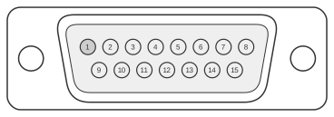
 15 pin D-SUB male connector at the Apple computer, looking into cable-side connector.
The Apple IIc (1984) video expansion port is a DB-15 female connector on the rear panel that exposes the internal Apple II digital timing and video signals to external display devices or video adapters. Unlike later Macintosh video connectors, it carries no analogue RGB — instead it provides raw timing signals from the TMG (timing generator), IOU, and VID hybrid chips, along with a composite NTSC output and a +12 V supply rail. The port is documented in Chapter 11 of the Apple IIc Technical Reference Manual (Second Edition), Table 11-17 and Figure 11-25. Despite sharing the same DB-15 shell as the Macintosh II DA-15 video connector, the signal assignments are entirely incompatible.
| Pin | Signal | Description |
|---|---|---|
| 1 | TEXT | Video text signal from TMG; set to inverse of GR, except in double high-resolution mode. |
| 2 | 14M | 14M master timing signal from the system oscillator. |
| 3 | SYNC* | Displays horizontal and vertical synchronization signal from IOU pin 39. |
| 4 | SEGB | Displays vertical counter bit from IOU pin 4; in text mode, indicates second low-order vertical counter; in graphics mode, indicates low-resolution. |
| 5 | 1V SOUND | One-volt sound signal from pin 5 of the audio hybrid circuit (AUD). |
| 6 | LDPS* | Video shift-register load enable from pin 12 of TMG. |
| 7 | WNDW* | Active area display blanking; includes both horizontal and vertical blanking. |
| 8 | +12V | Regulated +12 volts DC; can drive 300mA. |
| 9 | PRAS* | RAM row-address strobe from TMG pin 19. |
| 10 | GR | Graphics mode enable from IOU pin 2. |
| 11 | SEROUT* | Serialized character generator output from pin 1 of the 74LS166 shift register. |
| 12 | NTSC | Composite NTSC video signal from VID hybrid chip. |
| 13 | GND | Ground reference and supply. |
| 14 | VIDD7 | From 74LS374 video latch; causes half-dot shift high. |
| 15 | CREF | Color reference signal from TMG pin 3; 3.58 MHz. |
Signals
- TEXT — Video text mode signal generated by the TMG; logic inverse of GR except when double high-resolution mode is active.
- 14M — 14 MHz master clock from the system oscillator. This signal must be buffered within approximately 4 inches of the rear panel connector, preferably inside an enclosure directly attached to the panel.
- SYNC* — Combined horizontal and vertical synchronisation signal sourced from IOU pin 39; active-low.
- SEGB — Vertical counter bit from IOU pin 4. In text mode it indicates the second low-order vertical counter; in graphics mode it signals low-resolution graphics.
- 1V SOUND — Analogue audio output at approximately 1 V, taken from pin 5 of the audio hybrid circuit (AUD).
- LDPS* — Active-low load-enable pulse for the video shift register, from TMG pin 12.
- WNDW* — Active-low composite blanking signal covering both horizontal and vertical blanking intervals; defines the active display area.
- +12V — Regulated +12 VDC supply, rated at 300 mA maximum for external use.
- PRAS* — RAM row-address strobe from TMG pin 19; used by external circuits that need to track DRAM refresh timing.
- GR — Graphics mode enable from IOU pin 2; high when the system is in a graphics mode.
- SEROUT* — Serialised output of the character generator ROM, from pin 1 of the 74LS166 parallel-to-serial shift register; active-low.
- NTSC — Fully encoded composite NTSC video signal produced by the VID hybrid chip; suitable for driving a composite video input directly.
- GND — Ground reference for all signals and the +12 V supply.
- VIDD7 — Video data bit 7 from the 74LS374 video latch; when high, enables the half-dot horizontal shift used for colour fringing correction.
- CREF — 3.58 MHz colour burst reference clock from TMG pin 3; used by external circuits requiring NTSC colour subcarrier phase reference.
Notes
- The signals on the Apple IIc DB-15 connector are not the same as those on the Apple III, Apple IIGS, or Macintosh II DA-15 video connector. Despite the physically identical DB-15 shell, cross-connecting cables between these systems will not produce valid video and may damage the hardware.
- The 14 MHz signal (pin 2) and other high-frequency timing outputs must be buffered within approximately 4 inches of the rear panel, preferably inside an enclosure directly coupled to the connector.
- The +12 V supply on pin 8 is current-limited to 300 mA maximum; external adapters must not draw more than this without additional regulation.
- The connector is designated DB-15 female on the Apple IIc rear panel; an external adapter or display device therefore presents a DB-15 male plug.
References
- Apple IIc Technical Reference Manual (Second Edition) — Chapter 11, Table 11-17 and Figure 11-25; Apple Computer, Inc.