
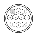
 10 pin mini-din female connector at the Matrox G450 videocard.
The Matrox Marvel G450 eTV is a late-1990s/early-2000s graphics and video-capture card that carries analogue video and stereo audio through two proprietary mini-DIN connectors: a 10-pin mini-DIN for A/V output and an 8-pin mini-DIN for A/V input. Two supplied dongle cables split each multi-pin connector into standard 4-pin S-Video, RCA composite, and 3.5 mm stereo audio jacks. Video decoding is handled by an on-board Samsung chip, with a Philips TV tuner module providing broadcast reception; simultaneous composite and S-Video output is supported. Both connectors are unique to the Marvel G450 eTV variant — the Matrox Millennium G450 (non-eTV) routes TV output through a VGA HD-15 adapter instead.
| Pin | Signal |
|---|---|
| 1 | Chroma (s-video) |
| 2 | Ground |
| 3 | Luminance (s-video) |
| 4 | RGB switching control |
| 5 | Composite sync |
| 6 | Ground |
| 7 | Composite video |
| 8 | Audio-left |
| 9 | Ground |
| 10 | Audio-right |
Notes
The table above covers the A/V OUT 10-pin mini-DIN (female) connector on the card’s rear bracket. A second A/V IN 8-pin mini-DIN (female) is also present for video capture; its pinout (from the same user guide, pp. 52–53) is: pin 1 = Chroma (S-Video), pin 2 = Audio-Right, pin 3 = GND, pin 4 = GND, pin 5 = GND, pin 6 = Luminance (S-Video), pin 7 = Composite Video, pin 8 = Audio-Left. The two connectors are not interchangeable and accept different dongle cables. Composite and S-Video lines on the output side may be driven simultaneously.
Signals
- Chroma (s-video) — S-Video C (chrominance) subcarrier signal, nominally 0.3 V peak-to-peak into 75 Ω.
- Luminance (s-video) — S-Video Y (luminance) signal, nominally 1 V peak-to-peak into 75 Ω.
- Composite video — CVBS (Colour, Video, Blanking and Sync) composite signal, 1 V peak-to-peak into 75 Ω; output is active simultaneously with the S-Video lines.
- Composite sync — Horizontal and vertical sync combined on a single line, used by certain displays and RGB-switching devices.
- RGB switching control — Control line used to switch external devices (e.g. SCART-equipped televisions) between RGB and composite input modes.
- Audio-left — Left-channel line-level stereo audio output.
- Audio-right — Right-channel line-level stereo audio output.
- Ground — Signal ground, shared by video and audio circuits (pins 2, 6, and 9 on the output connector).
References
- Matrox Marvel G450 eTV User Guide (P/N 10713-301-0110) — Matrox Graphics Inc., 2002-01-14; pages 52–53 contain the official A/V IN and A/V OUT pin tables.