
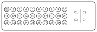
 35 pin MOLEX “MicroCross” female connector at the videocard/monitor.
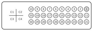 35 pin MOLEX “MicroCross” male connector at the cable.
The VESA Plug and Display Analog/Digital connector (P&D-A/D), commercially marketed by InFocus and projector vendors as M1-DA, is the analogue-plus-digital variant of the P&D standard first ratified by VESA in June 1997. It consolidates TMDS digital video (Silicon Image PanelLink protocol), analogue RGB via four coaxial lines, USB, optional IEEE 1394 (FireWire), and DDC/I²C into a single 30-pin D-shell body supplemented by five coaxial contacts (C1–C5). The digital TMDS section is pin-compatible with the digital-only P&D-D variant, and the standard is explicitly compatible with DVI via a passive mechanical adapter, though care is required because the P&D Hot Plug Detect line may carry up to +20 V whereas DVI HPD is rated at +5 V. The connector was assigned VESA interface code 06h in the EDID Display Information Extension Block standard (August 2001) and shares its TMDS encoding with DFP and DVI; it was largely superseded by DVI by 2004.
| Pin | Name |
|---|---|
| 1 | TMDS Data 2 + |
| 2 | TMDS Data 2 - |
| 3 | TMDS Data return |
| 4 | Hz and Vt Sync return |
| 5 | Horizontal sync/Composite sync |
| 6 | Vertical sync |
| 7 | TMDS Clock return |
| 8 | Charge power |
| 9 | 1394 pair A, data - |
| 10 | 1394 pair A, data + |
| 11 | TMDS Data 1 + |
| 12 | TMDS Data 1 - |
| 13 | TMDS Data 1 return |
| 14 | TMDS Clock + |
| 15 | TMDS Clock - |
| 16 | USB data + |
| 17 | USB data - |
| 18* | 1394 outer shield (optional) & Charge Power return |
| 19 | 1394 Vg |
| 20 | 1394 Vp |
| 21 | TMDS Data 0 + |
| 22 | TMDS Data 0 - |
| 23 | TMDS Data 0 return |
| 24 | Stereo sync (TTL) |
| 25 | DDC return & Stereo Sync return |
| 26 | DDC data (SDA) |
| 27 | DDC clock (SCL) |
| 28 | +5 VDC |
| 29 | 1394 pair B, clock + |
| 30 | 1394 pair B, clock - |
| C1 | Red Video |
| C2 | Green Video |
| C3 | Pixel clock (optional) |
| C4 | Blue Video |
| C5 | Video / Pixel Clock Ground |
Notes
- The P&D-A/D (M1-DA) uses a D-shaped shell, distinguishing it from the earlier EVC (Enhanced Video Connector, 1994) which shares the same 30-pin-plus-quad-coax contact layout but uses an isosceles-trapezoid shell.
- The digital TMDS section (pins 1–3, 7, 11–15, 21–23) is pin-compatible with the digital-only P&D-D variant; a passive mechanical adapter connects P&D-A/D to a DVI-I port.
- HPD voltage caution: the Hot Plug Detect line on P&D may carry up to +20 V; DVI HPD is specified at +5 V. Adapters must leave the HPD line unconnected or clamp it to 5 V to avoid damaging DVI host hardware.
- USB support is per USB Specification v1.0 (January 1996); DDC is per VESA DDC/CI Standard v1 (August 1998). Both are optional features of the P&D standard.
- IEEE 1394 (FireWire) support is optional; pins 9–10 (pair A, data), 18 (outer shield/charge power return), 19–20 (Vg/Vp), and 29–30 (pair B, clock) carry the 1394 interface.
- The coaxial contacts C1–C4 carry analogue RGB video; C5 is the shared video/pixel clock ground return.
- The +5 VDC supply on pin 28 powers DDC and related circuitry. Pin 8 carries charge power for optional peripheral charging.
- VESA assigned interface code 06h to P&D in the EDID Display Information Extension Block standard (VESA DI-EXT, Release A, August 2001).
Signals
- TMDS Data 2+/− — Positive and negative conductors of TMDS data channel 2 (differential pair; single-link TMDS per Silicon Image PanelLink)
- TMDS Data return — Shield/return for TMDS data pairs
- Hz and Vt Sync return — Ground return for horizontal and vertical synchronisation signals
- Horizontal sync/Composite sync — Analogue horizontal synchronisation or composite sync signal
- Vertical sync — Analogue vertical synchronisation signal
- TMDS Clock return — Shield/return for the TMDS clock pair
- Charge power — Optional power rail for peripheral charging
- 1394 pair A, data−/+ — IEEE 1394 (FireWire) data pair A, negative and positive conductors
- TMDS Data 1+/− — Positive and negative conductors of TMDS data channel 1
- TMDS Data 1 return — Shield/return for TMDS data channel 1
- TMDS Clock+/− — Positive and negative conductors of the TMDS pixel clock pair
- USB data+/− — USB 1.0 data lines (positive and negative)
- 1394 outer shield — IEEE 1394 outer cable shield, also serves as charge power return (optional; pin 18*)
- 1394 Vg — IEEE 1394 ground reference voltage
- 1394 Vp — IEEE 1394 power voltage
- TMDS Data 0+/− — Positive and negative conductors of TMDS data channel 0
- TMDS Data 0 return — Shield/return for TMDS data channel 0
- Stereo sync (TTL) — TTL-level synchronisation signal for stereo (3D) display glasses
- DDC return & Stereo Sync return — Ground return shared by the DDC bus and stereo sync signal
- DDC data (SDA) — I²C data line for Display Data Channel (carries EDID from the display)
- DDC clock (SCL) — I²C clock line for Display Data Channel
- +5 VDC — 5 V supply for DDC and peripheral logic
- 1394 pair B, clock+/− — IEEE 1394 clock pair B, positive and negative conductors
- C1 – Red Video — Analogue red video signal (coaxial contact)
- C2 – Green Video — Analogue green video signal (coaxial contact)
- C3 – Pixel clock (optional) — Optional analogue pixel clock (coaxial contact)
- C4 – Blue Video — Analogue blue video signal (coaxial contact)
- C5 – Video / Pixel Clock Ground — Coaxial ground return for analogue video and pixel clock signals