
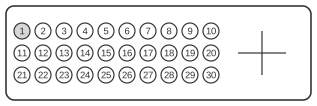
 30 pin MOLEX “MicroCross” female connector at the videocard/monitor.
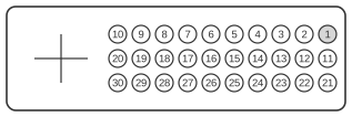 30 pin MOLEX “MicroCross” male connector at the cable.
The VESA Plug and Display (P&D) standard, Version 1.0, was ratified on 11 June 1997 and defines two connector variants: P&D-D (digital only) and P&D-A/D (analogue and digital). The P&D-D variant uses a 30-pin MOLEX MicroCross connector with a D-shaped shell — distinguishing it from the earlier VESA Enhanced Video Connector (EVC, 1994), which shares the same 30-pin-plus-quad-coax contact layout but with a trapezoidal shell. Digital video is carried via Silicon Image’s TMDS (Transition Minimised Differential Signalling) protocol, the same single-link protocol later standardised in DVI; a single link supports pixel clocks up to 165 MHz. The connector also optionally accommodates USB, IEEE 1394 (FireWire), and DDC2B (for EDID plug-and-play), making it a versatile interface for flat-panel displays of the late 1990s.
| Pin | Name |
|---|---|
| 1 | TMDS Data 2 + |
| 2 | TMDS Data 2 - |
| 3 | TMDS Data return |
| 4 | Unused |
| 5 | Unused |
| 6 | Unused |
| 7 | TMDS Clock return |
| 8 | Charge power (optional) |
| 9 | 1394 pair A, data - |
| 10 | 1394 pair A, data + |
| 11 | TMDS Data 1 + |
| 12 | TMDS Data 1 - |
| 13 | TMDS Data 1 return |
| 14 | TMDS Clock + |
| 15 | TMDS Clock - |
| 16 | USB data + |
| 17 | USB data - |
| 18 | 1394 outer shield (optional) & Charge Power return |
| 19 | 1394 Vg |
| 20 | 1394 Vp |
| 21 | TMDS Data 0 + |
| 22 | TMDS Data 0 - |
| 23 | TMDS Data 0 return |
| 24 | Unused |
| 25 | DDC return |
| 26 | DDC data (SDA) |
| 27 | DDC clock (SCL) |
| 28 | +5 VDC |
| 29 | 1394 pair B, clock + |
| 30 | 1394 pair B, clock - |
Notes
The P&D-D connector uses a D-shaped shell to distinguish it from the older EVC trapezoid shell; the two share the same 30-pin contact layout and are not mechanically interchangeable. The digital TMDS section is pin-compatible with P&D-A/D, enabling passive adapters between the two variants. DVI Revision 1.0 explicitly states that P&D implementations connect to DVI via a simple adapter, but cautions that the P&D Hot Plug Detect (HPD) pin may carry up to +20 V, whereas DVI HPD is +5 V; any adapter must therefore leave HPD unconnected or clamp it to 5 V. DDC2B is mandatory for plug-and-play EDID; the +5 VDC on pin 28 powers DDC circuitry in the display. IEEE 1394 and USB support are optional. The VESA DI-EXT standard (August 2001) assigns connector code 06h to P&D for use in EDID extension blocks.
Signals
- TMDS Data 0±, 1±, 2± — three TMDS differential data pairs (Silicon Image PanelLink); current-drive differential signalling with 8b/10b DC-balanced encoding; supports single-link operation up to 165 MHz pixel clock
- TMDS Data return — shield/return conductor shared by the adjacent TMDS data pair
- TMDS Clock± — TMDS differential clock pair, one per single link
- TMDS Clock return — shield/return conductor for the clock pair
- DDC data (SDA) — I²C serial data line for VESA DDC2B; used to read EDID from the display
- DDC clock (SCL) — I²C serial clock line for VESA DDC2B
- DDC return — ground return for DDC signals
- +5 VDC — 5 V supply from the host, powering DDC and EDID circuitry in the display
- USB data+, data− — USB 1.x differential data pair (optional); carries USB signalling between host and display hub
- 1394 pair A, data± — IEEE 1394 (FireWire) differential data pair A (optional)
- 1394 pair B, clock± — IEEE 1394 differential clock pair B (optional)
- 1394 Vp — IEEE 1394 power supply line (optional)
- 1394 Vg — IEEE 1394 power ground line (optional)
- 1394 outer shield — optional outer shield for IEEE 1394 cabling; may also carry Charge Power return
- Charge power — optional auxiliary power delivery to the display (pin 8)
- Unused — pins 4, 5, 6, and 24 are reserved and unpopulated in the P&D-D variant