
X.21 is a fully differential, balanced serial interface defined by ITU-T X.21, using a 15-pin D-sub (DB-15) connector and V.11 electrical characteristics. It carries data, control, timing, and indication circuits as differential signal pairs, with a single clock serving both transmit and receive directions. This adapter cable connects a DB-25 serial port — such as those found on older routers, DSUs, or serial expansion cards — to a DB-15 X.21 port on network equipment or a modem, allowing synchronous WAN connections at rates up to 10 Mbps. X.21 was widely deployed on European public data networks and remains common in the UK for leased-line access.
 25 pin D-SUB male connector
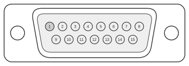 15 pin D-SUB male connector
| Name | Pin | Direction | Pin | Name | Description |
|---|---|---|---|---|---|
| 2 | 2 | ||||
| 3 | 4 | ||||
| 4 | 3 | ||||
| 6 | 12 | ||||
| 7 | 8 | ||||
| 8 | 5 | ||||
| 14 | 9 | ||||
| 15 | 6 | ||||
| 16 | 11 | ||||
| 20 | 10 | ||||
| 21 | 13 |
Signals
The DB-15 connector pin assignments follow the ITU-T X.21 standard:
- Transmit A/B (DB-15 pins 2/9) — differential pair carrying data from DTE to DCE
- Control A/B (DB-15 pins 3/10) — differential pair; DTE signals readiness to the network
- Receive A/B (DB-15 pins 4/11) — differential pair carrying data from DCE to DTE
- Indication A/B (DB-15 pins 5/12) — differential pair; DCE signals network status to the DTE
- Signal Timing A/B (DB-15 pins 6/13) — differential clock pair; DCE supplies timing for both transmit and receive data
- Byte Timing A/B (DB-15 pins 7/14) — differential pair indicating octet boundaries; function unknown for this adapter
- Signal Ground (DB-15 pin 8) — reference ground; corresponds to DB-25 pin 7
- Shield (DB-15 pin 1) — cable screen/chassis ground; not listed in the mapping table above
Notes
- This adapter connects a DB-25 serial port to a DB-15 X.21 port, for example linking an older router or serial card to a leased-line modem or network termination unit.
- X.21 uses fully differential V.11 (RS-422) signalling on all data, control, and timing circuits, giving good noise immunity and allowing operation at rates up to 10 Mbps.
- All X.21 signals are carried as balanced pairs (A/B); both conductors of each pair must be connected for correct operation.
- The single Signal Timing clock (DB-15 pins 6/13) is supplied by the DCE and governs both transmit and receive data timing.
- DB-25 pin assignments in the left column represent X.21-compatible signals presented on the DB-25 port; the specific signal-to-pin mapping on the DB-25 side varies by equipment manufacturer.
References
- ITU-T Recommendation X.21: Interface between DTE and DCE for synchronous operation on public data networks
- ISO 4903 — 15-pole DTE/DCE interface connector and contact number assignments (International Organization for Standardization)