
APC PDU Serial Console Cable
The APC (American Power Conversion) AP7920 and related switched rack PDUs provide a serial console port as an RJ12 (6P6C) female socket on the front panel. This port is used for firmware recovery, password reset, and limited management functions over a TIA-232 asynchronous serial link. The cable connects the PDU’s RJ12 port to a host computer’s DE-9 (DB9) female serial port and carries only four active conductors; the two outer pins of the RJ12 connector (pins 1 and 6) are unused. APC supplies this cable under part number 940-0144. Serial settings are fixed at 9600 baud, 8 data bits, no parity, and no flow control.
Connector on the device itself:
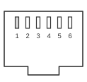 6 pin RJ12 (6P6C) female connector on the front of the PDU
Connector on the server
 9 PIN D-SUB FEMALE to the Server
Wiring
| APC/PDU name | RJ12 pin | Direction | DB9 Pin | Serial Name | Description |
|---|---|---|---|---|---|
| na | 1 | na | 1 | na | Unknown |
| GND | 2 | — | 5 | GND | Ground (using either is fine) |
| RX | 3 | ← | 2 | RX | Server to PDU comms 9600, 8N1 |
| TX | 4 | → | 3 | RX | PDU to Server comms 9600, 8N1 |
| GND | 5 | — | 5 | GND | Ground (using either is fine) |
| na | 6 | — | na | na | Unknown |
Signals
- RJ12 pin 1 — function unknown; not connected in APC cable 940-0144
- GND — signal ground; either RJ12 pin 2 or pin 5 may be used; they need not be interconnected
- RX — receive data (host to PDU); RJ12 pin 3 → DB9 pin 2
- TX — transmit data (PDU to host); RJ12 pin 4 → DB9 pin 3
- RJ12 pin 6 — function unknown; not connected in APC cable 940-0144
Notes
Only four conductors are active; a 4-conductor flat cable is sufficient as the outer two pins (1 and 6) of the RJ12 are unused. Both ground pins (RJ12 2 and 5) connect to DB9 pin 5; either one alone is adequate.
Serial port settings: 9600 baud, 8 data bits, no parity, no flow control.
Password recovery procedure for APC switched rack PDUs:
- Ensure the unit is powered up and has completed its boot sequence (this can take around 100 seconds).
- Connect the RJ12/DB9 cable and configure the terminal for 9600, 8N1, no flow control.
- Press the reset button and release it.
- Wait for the orange LED to begin flashing.
- Press the reset button again before the LED stops flashing.
- The serial port will now accept login with username and password both set to
apcfor approximately 30 seconds. - Wait 2–3 seconds for the LED to change state (or press Return repeatedly on the terminal).
- Press Return to obtain the
Username:prompt.
Some APC units incorporate a watchdog that resets the unit every 7 to 9 minutes if the device cannot reach its default gateway or detect Ethernet traffic.
Certain security configuration steps can only be completed through the web interface and are not accessible over the serial port or SSH connection (as of hardware/software/network versions B2/265/264, circa 2005–2006).
References
- APC Switched Rack PDU (AP7902/AP7911) Installation and Quick-Start Manual — American Power Conversion; the AP79xx serial console cable (part 940-0144).
- TIA/EIA-232-F — RS-232 serial console signalling (9600 8N1).