
 X.21 DCE Cable Pinout (DB-60 to DB-15)
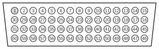
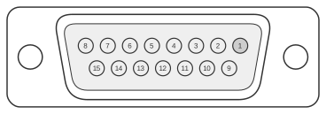
The Cisco X.21 DCE cable (part number CAB-X21FC) connects the 60-pin high-density DB-60 connector on Cisco 4000, 4500, and 4700 series routers to a 15-pin D-sub (DB-15) port on an X.21 DTE device. ITU-T X.21 (1992) defines a fully balanced, differential interface using V.11 electrical characteristics, capable of data rates up to 10 Mbps and commonly used at 64 kbps to 256 kbps on European public data networks. In DCE mode the router supplies the timing signal; a female DB-15 receptacle is used at the network end, and the interface type is selected by shorting the MODE_0/MODE_DCE pins on the DB-60 connector.
| 60 Pin1 | Signal | Description | Direction | 15 Pin | Signal |
|---|---|---|---|---|---|
| J1-48 J1-47 | GND MODE_2 | Shorting group | - | - | - |
| J1-46 | Shield_GND | Single | - | J2-1 | Shield GND |
| J1-28 J1-27 | RxD/TxD+ RxD/TxD- | Twisted pair no. 6 | ← ← | J2-2 J2-9 | Transmit+ Transmit- |
| J1-1 J1-2 | CTS/RTS+ CTS/RTS- | Twisted pair no. 1 | ← ← | J2-3 J2-10 | Control+ Control- |
| J1-11 J1-12 | TxD/RxD+ TxD/RxD- | Twisted pair no. 3 | → → | J2-4 J2-11 | Receive+ Receive- |
| J1-9 J1-10 | RTS/CTS+ RTS/CTS- | Twisted pair no. 2 | → → | J2-5 J2-12 | Indication+ Indication- |
| J1-24 J1-23 | TxC/RxC+ TxC/RxC- | Twisted pair no. 4 | → → | J2-6 J2-13 | Timing+ Timing- |
| J1-15 Shield | Control_GND - | Twisted pair no. 5 | - - | J2-8 Shield | Control GND - |
Notes
- Arrows indicate signal direction: → indicates DTE to DCE, and ← indicates DCE to DTE.
- (1) Any pin not referenced is not connected.
- The DB-60 shorting group at J1-47/J1-48 (GND/MODE_2) selects X.21 mode; additional shorting pins (MODE_0, MODE_DCE) in the J1-46–J1-56 range set DCE operation.
- The DB-15 network-end connector is a female receptacle (FCE suffix) in DCE cables; DTE cables (CAB-X21MT) use a male plug.
- All data and timing signals are fully differential (V.11/RS-422 electrical characteristics), giving good EMI resistance and allowing operation over longer distances than single-ended interfaces.
- The Cisco router acts as DCE and supplies the timing (Timing+/- on J1-24/J1-23 → DB-15 pins 6/13) to the attached DTE device.
Signals
- GND MODE_2 — Shorting pair that selects X.21 as the active serial interface type on the DB-60 connector.
- Shield_GND — Chassis/shield ground connected from DB-60 J1-46 to DB-15 pin 1.
- RxD/TxD+, RxD/TxD- — Receive data from the DTE perspective; presented as Transmit+ / Transmit- (DB-15 pins 2/9) to the attached DTE. In DCE mode the router drives this pair outbound to the DTE.
- CTS/RTS+, CTS/RTS- — Control circuit (DB-15 pins 3/10); in X.21 this circuit conveys call-control signalling from the DCE to the DTE.
- TxD/RxD+, TxD/RxD- — Transmit data from the DTE perspective; received by the router (DCE) on DB-60 J1-11/J1-12 and presented as Receive+ / Receive- on DB-15 pins 4/11.
- RTS/CTS+, RTS/CTS- — Indication circuit (DB-15 pins 5/12); conveys status or indication signals from the DCE back to the DTE.
- TxC/RxC+, TxC/RxC- — Timing (clock) signal supplied by the router (DCE) to the DTE on DB-15 pins 6/13; a single clock is used for both transmit and receive synchronisation in X.21.
- Control_GND — Control/signal ground reference for the differential pairs; DB-60 J1-15 to DB-15 pin 8.