
 9 PIN D-SUB FEMALE to the Computer
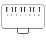 RJ45 MALE CONNECTOR to the Adtran CSU
ADTRAN TSU-series channel service units provide a Control In / Chain In port using an RJ-48 connector (physically identical to RJ-45) for out-of-band EIA-232 serial management. This port accepts a PC terminal or modem connection via a proprietary adapter (ADTRAN part 3196ADPT001) that converts the eight-position modular plug to a DB-9 female socket. The cable carries ground, RTS/CTS flow control, and the Receive/Transmit data lines; pins 4, 6, and 7 on the RJ-45 side are unused. The same connector pinout was used consistently across the TSU 120, TSU 120e, and TSU 600 product lines.
| RJ45 | DB9 |
|---|---|
| 1 | 5 |
| 2 | 7 |
| 3 | 2 |
| 4 | N/C |
| 5 | 3 |
| 6 | N/C |
| 7 | N/C |
| 8 | 8 |
| N/C | 9 |
Signals
RJ-45 side (Adtran CSU Control In / Chain In port):
- GND — Chassis ground (RJ-45 pin 1 → DB-9 pin 5)
- RTS — Request to Send; flow control output from the CSU (RJ-45 pin 2 → DB-9 pin 7)
- RXDATA — Receive Data; data received by the TSU from the PC (RJ-45 pin 3 → DB-9 pin 2)
- TXDATA — Transmit Data; data transmitted by the TSU to the PC (RJ-45 pin 5 → DB-9 pin 3)
- CTS — Clear to Send; flow control input to the CSU (RJ-45 pin 8 → DB-9 pin 8)
- RJ-45 pins 4, 6, and 7 are unused on all TSU-series units
- DB-9 pin 9 (RI) is not connected
Notes
- The RJ-48 connector (AMP# 555164-2, ADTRAN part 61202129L1-1) is mechanically identical to RJ-45 and accepts standard 8P8C plugs.
- ADTRAN requires its own proprietary adapter (3196ADPT001); a standard Cisco console rollover cable will not work directly with the ADTRAN Control In port.
- The port operates at EIA-232 signal levels. Default terminal settings for TSU-series units are 9600 baud, 8 data bits, no parity, 1 stop bit.
- The Chain In variant of the same port allows daisy-chaining a second TSU unit using the same cable and pinout.
- TSU 120e models also include a 10BaseT Ethernet port for SNMP management as an alternative management path.