
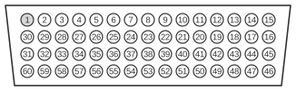
 Cisco EIA/TIA-530 DTE Cable (DB60 to DB25)
EIA/TIA-530 (finalised 1987, revised as TIA-530-A in 1992) is a high-speed synchronous serial interface standard that reuses RS-422 balanced differential electrical signalling within a DB-25 connector — offering the performance of the larger EIA/TIA-449 (DB-37) design in a more compact housing. Cisco serial WAN cards use a proprietary 60-pin DB-60 high-density connector on the router end; plugging in the appropriate cable selects the active signalling standard, with EIA/TIA-530 available in DTE mode only — no DCE variant exists. The network end is a standard DB-25 male plug, and the cable carries differential pairs for transmit data, receive data, request to send, clear to send, data set ready, data carrier detect, data terminal ready, transmit clock, receive clock, and transmit clock external, with a local loopback (LL) control line.
| 60 Pin1 | Signal | 25 Pin | Signal | Direction DTE DCE2 |
|---|---|---|---|---|
| J1-11 J1-12 | TxD/RxD+ TxD/RxD- | J2-2 J2-14 | BA(A), TxD+ BA(B), TxD- | → → |
| J1-28 J1-27 | RxD/TxD+ RxD/TxD- | J2-3 J2-16 | BB(A), RxD+ BB(B), RxD- | ← ← |
| J1-9 J1-10 | RTS/CTS+ RTS/CTS- | J2-4 J2-19 | CA(A), RTS+ CA(B), RTS- | → → |
| J1-1 J1-2 | CTS/RTS+ CTS/RTS- | J2-5 J2-13 | CB(A), CTS+ CB(B), CTS- | ← ← |
| J1-3 J1-4 | DSR/DTR+ DSR/DTR- | J2-6 J2-22 | CC(A), DSR+ CC(B), DSR- | ← ← |
| J1-46 J1-47 | Shield_GND MODE_2 | J2-1 - | Shield - | Shorted |
| J1-48 J1-49 | GND MODE_1 | - - | - - | Shorted |
| J1-5 J1-6 | DCD/DCD+ DCD/DCD- | J2-8 J2-10 | CF(A), DCD+ CF(B), DCD- | ← ← |
| J1-24 J1-23 | TxC/RxC+ TxC/RxC- | J2-15 J2-12 | DB(A), TxC+ DB(B), TxC- | ← ← |
| J1-26 J1-25 | RxC/TxCE+ RxC/TxCE- | J2-17 J2-9 | DD(A), RxC+ DD(B), RxC- | ← ← |
| J1-44 J1-45 | LL/DCD Circuit_GND | J2-18 J2-7 | LL Circuit_GND | → - |
| J1-7 J1-8 | DTR/DSR+ DTR/DSR- | J2-20 J2-23 | CD(A), DTR+ CD(B), DTR- | → → |
| J1-13 J1-14 | TxCE/TxC+ TxCE/TxC- | J2-24 J2-11 | DA(A), TxCE+ DA(B), TxCE- | → → |
Notes
- Arrows indicate signal direction: → indicates DTE to DCE, and ← indicates DCE to DTE.
- (1) Any pin not referenced is not connected.
- (2) The EIA-530 interface cannot be operated in DCE mode. A DCE cable is not available for the EIA-530 interface.
- All data and clock signals use RS-422 balanced (differential) pairs; the A wire carries the positive phase and the B wire the negative phase.
- MODE pins (J1-46 through J1-49) on the DB-60 select the interface type and DTE/DCE mode; they are shorted internally by the cable and are not connected to the network end.
- The Cisco part number for this cable is CAB-530MT (MT = male termination, indicating DTE mode).
Signals
- TxD+/TxD− — Transmitted Data, differential pair; data sent from the DTE (router) to the DCE (network equipment). EIA-530 circuit BA.
- RxD+/RxD− — Received Data, differential pair; data received by the DTE from the DCE. EIA-530 circuit BB.
- RTS+/RTS− — Request To Send, differential pair; DTE asserts this circuit to signal readiness to transmit. EIA-530 circuit CA.
- CTS+/CTS− — Clear To Send, differential pair; asserted by the DCE to grant the DTE permission to transmit. EIA-530 circuit CB.
- DSR+/DSR− — Data Set Ready, differential pair; asserted by the DCE to indicate it is operational and connected. EIA-530 circuit CC.
- DCD+/DCD− — Data Carrier Detect, differential pair; asserted by the DCE when a valid carrier is detected on the line. EIA-530 circuit CF.
- DTR+/DTR− — Data Terminal Ready, differential pair; asserted by the DTE to indicate it is ready for operation. EIA-530 circuit CD.
- TxC+/TxC− — Transmit Clock (from DCE), differential pair; clock provided by the DCE to synchronise DTE transmission. EIA-530 circuit DB.
- RxC+/RxC− — Receive Clock, differential pair; clock provided by the DCE to synchronise DTE reception. EIA-530 circuit DD.
- TxCE+/TxCE− — Transmit Clock External (from DTE), differential pair; clock sourced by the DTE when the DTE is providing its own transmit timing. EIA-530 circuit DA.
- LL — Local Loopback; single-ended control signal asserted by the DTE to request a local loopback test at the DCE. EIA-530 circuit LL.
- Shield_GND — Chassis/shield ground; connected to the cable shield and connector shell.
- Circuit_GND — Signal reference ground for all circuits on the cable.
- MODE_1 / MODE_2 — DB-60 mode-selection pins; shorted internally by the cable to configure the interface type on the router module. Not connected at the network end.