
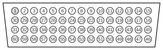
 V.35 DTE Cable Pinout (DB60 to 34-Pin)
The Cisco V.35 DTE cable connects the proprietary 60-pin high-density DB-60 connector on the router end (J1) to a 34-pin Winchester-type (ISO 2593 / MRAC-34) connector at the network end (J2). The ITU-T V.35 recommendation (October 1984, now withdrawn) originally specified group-band modulation at 48 kbit/s, but the V.35 connector interface became a pervasive WAN de facto standard used at speeds from 64 kbit/s up to 2 Mbit/s and beyond. Data and clock signals use balanced differential V.11 signalling, whilst modem control signals use single-ended V.28. The DTE cable carries a male plug at the network end; the DCE device (typically a CSU/DSU) supplies the transmit clock, and the Cisco router operates as DTE.
| 60 Pin1 | Signal | Description | Direction | 34 Pin | Signal |
|---|---|---|---|---|---|
| J1-49 J1-48 | MODE_1 GND | Shorting group | - | - | - |
| J1-50 J1-51 J1-52 | MODE_0 GND MODE_DCE | Shorting group | - | - | - |
| J1-53 J1-54 J1-55 J1-56 | TxC/NIL RxC_TxCE RxD/TxD GND | Shorting group | - | - | - |
| J1-46 | Shield_GND | Single | - | J2-A | Frame GND |
| J1-45 Shield | Circuit_GND - | Twisted pair no. 12 | - - | J2-B Shield | Circuit GND - |
| J1-42 Shield | RTS/CTS - | Twisted pair no. 9 | → - | J2-C Shield | RTS - |
| J1-35 Shield | CTS/RTS - | Twisted pair no. 8 | ← - | J2-D Shield | CTS - |
| J1-34 Shield | DSR/DTR - | Twisted pair no. 7 | ← - | J2-E Shield | DSR - |
| J1-33 Shield | DCD/LL - | Twisted pair no. 6 | ← - | J2-F Shield | RLSD - |
| J1-43 Shield | DTR/DSR - | Twisted pair no. 10 | → - | J2-H Shield | DTR - |
| J1-44 Shield | LL/DCD - | Twisted pair no. 11 | → - | J2-K Shield | LT - |
| J1-18 J1-17 | TxD/RxD+ TxD/RxD- | Twisted pair no. 1 | → → | J2-P J2-S | SD+ SD- |
| J1-28 J1-27 | RxD/TxD+ RxD/TxD- | Twisted pair no. 5 | ← ← | J2-R J2-T | RD+ RD- |
| J1-20 J1-19 | TxCE/TxC+ TxCE/TxC- | Twisted pair no. 2 | → → | J2-U J2-W | SCTE+ SCTE- |
| J1-26 J1-25 | RxC/TxCE+ RxC/TxCE- | Twisted pair no. 4 | ← ← | J2-V J2-X | SCR+ SCR- |
| J1-24 J1-23 | TxC/RxC+ TxC/RxC- | Twisted pair no. 3 | ← ← | J2-Y J2-AA | SCT+ SCT- |
Notes
- Arrows indicate signal direction: → indicates DTE to DCE, and ← indicates DCE to DTE.
- (1) Any pin not referenced is not connected.
- V.35 uses lettered pin designations (A, B, C, P, R, S, T, U, V, W, X, Y, AA, etc.) on the ISO 2593 Winchester connector, not numeric positions.
- The DB-60 connector on the Cisco router end selects the interface type and DTE/DCE mode via shorting groups on pins J1-49 through J1-56. Pins J1-50/J1-51/J1-52 (MODE_0/GND/MODE_DCE) must be shorted appropriately for V.35 DTE operation.
- The Winchester 34-pin connector’s male plug (DTE end) mates with the female receptacle on the DCE device.
Signals
- Shield_GND — Frame/chassis ground; connects DB-60 pin J1-46 to Winchester pin A.
- Circuit_GND — Signal reference ground for all circuits.
- RTS — Request to Send; DTE asserts to indicate readiness to transmit.
- CTS — Clear to Send; DCE asserts to grant DTE permission to transmit.
- DSR — Data Set Ready; DCE asserts to indicate it is operational.
- DCD / RLSD — Data Carrier Detect (Received Line Signal Detect); DCE asserts when a carrier is detected.
- DTR — Data Terminal Ready; DTE asserts to indicate it is ready for communication.
- LL / LT — Local Loopback (Loop Test); DTE asserts to request a local loopback test at the DCE.
- SD+ / SD− — Send Data (balanced differential pair); carries transmitted data from DTE to DCE.
- RD+ / RD− — Receive Data (balanced differential pair); carries received data from DCE to DTE.
- SCTE+ / SCTE− — Serial Clock Transmit External (balanced differential pair); DTE-sourced transmit clock returned to DCE for synchronisation.
- SCR+ / SCR− — Serial Clock Receive (balanced differential pair); receive clock provided by DCE to DTE.
- SCT+ / SCT− — Serial Clock Transmit (balanced differential pair); transmit clock provided by DCE to DTE.