
 EIA/TIA-449 DTE Cable Pinout (DB-60 to DB-37)
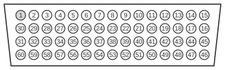
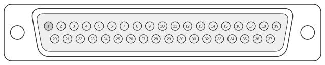
The Cisco EIA/TIA-449 DTE cable connects the 60-pin high-density DB-60 connector on Cisco 4000, 4500, and 4700 series routers to a 37-pin D-sub (DB-37) network device. EIA/TIA-449 (RS-449) is a general-purpose serial interface standard using RS-422 balanced differential signalling for primary data and clock circuits and RS-423 unbalanced signalling for control circuits, supporting throughput up to 10 Mbps. It was designed as a higher-performance replacement for EIA/TIA-232 and is related to the V.36 modem standard, though in practice it was largely superseded by EIA/TIA-530, which offers equivalent electrical performance in a smaller DB-25 housing. The DTE cable carries a male DB-37 plug at the network end; the router end uses the DB-60 connector common to all Cisco classic WAN serial cables, with shorting pins on the DB-60 selecting the interface type and mode.
| 60 Pin1 | Signal | Description | Direction | 37 Pin | Signal |
|---|---|---|---|---|---|
| J1-49 J1-48 | MODE_1 GND | Shorting group | - | - | - |
| J1-51 J1-52 | GND MODE_DCE | Shorting group | - | - | - |
| J1-46 | Shield_GND | Single | - | J2-1 | Shield GND |
| J1-11 J1-12 | TxD/RxD+ TxD/RxD- | Twisted pair no. 6 | → → | J2-4 2-22 | SD+ SD- |
| J1-24 J1-23 | TxC/RxC+ TxC/RxC- | Twisted pair no. 9 | ← ← | J2-5 J2-23 | ST+ ST- |
| J1-28 J1-27 | RxD/TxD+ RxD/TxD- | Twisted pair no. 11 | ← ← | J2-6 J2-24 | RD+ RD- |
| J1-9 J1-10 | RTS/CTS+ RTS/CTS- | Twisted pair no. 5 | → → | J2-7 J2-25 | RS+ RS- |
| J1-26 J1-25 | RxC/TxCE+ RxC/TxCE- | Twisted pair no. 10 | ← ← | J2-8 J2-26 | RT+ RT- |
| J1-1 J1-2 | CTS/RTS+ CTS/RTS- | Twisted pair no. 1 | ← ← | J2-9 J2-27 | CS+ CS- |
| J1-44 J1-45 | LL/DCD Circuit_GND | Twisted pair no. 12 | → - | J2-10 J2-37 | LL SC |
| J1-3 J1-4 | DSR/DTR+ DSR/DTR- | Twisted pair no. 2 | ← ← | J2-11 J2-29 | DM+ DM- |
| J1-7 J1-8 | DTR/DSR+ DTR/DSR- | Twisted pair no. 4 | → → | J2-12 J2-30 | TR+ TR- |
| J1-5 J1-6 | DCD/DCD+ DCD/DCD- | Twisted pair no. 3 | ← ← | J2-13 J2-31 | RR+ RR- |
| J1-13 J1-14 | TxCE/TxC+ TxCE/TxC- | Twisted pair no. 7 | → → | J2-17 J2-35 | TT+ TT- |
| J1-15 J1-16 | Circuit_GND Circuit_GND | Twisted pair no. 9 | - - | J2-19 J2-20 | SG RC |
Notes
- Arrows indicate signal direction: → indicates DTE to DCE, and ← indicates DCE to DTE.
- (1) Any pin not referenced is not connected.
- The DB-60 shorting group pins (MODE_0, MODE_1, GND, MODE_DCE in the J1-46–J1-52 range) determine which serial interface standard and which DTE/DCE mode is active; for EIA/TIA-449 DTE the appropriate pins are shorted by the cable itself.
- Primary data and clock signals use RS-422 balanced differential pairs; some link-management control signals use RS-423 unbalanced signalling.
- The network end of the DTE cable carries a male DB-37 plug; the corresponding DCE cable (CAB-449FC) carries a female DB-37 receptacle.
- All signals are transmitted as twisted pairs on the DB-60 side, numbered as listed in the Description column.
Signals
- SD+/SD- — Send Data (positive/negative); balanced differential pair carrying serial data transmitted from the DTE (router) to the DCE network device (DB-37 pins 4/22).
- ST+/ST- — Send Timing; clock signal provided by the DCE to synchronise DTE transmit data (DB-37 pins 5/23).
- RD+/RD- — Receive Data; balanced differential pair carrying serial data received by the DTE from the DCE (DB-37 pins 6/24).
- RS+/RS- — Request to Send; DTE asserts this control signal to request permission to transmit (DB-37 pins 7/25).
- RT+/RT- — Receive Timing; clock signal provided by the DCE for synchronisation of received data (DB-37 pins 8/26).
- CS+/CS- — Clear to Send; DCE asserts this signal in response to RS, granting the DTE permission to transmit (DB-37 pins 9/27).
- LL — Local Loopback; DTE-asserted control signal used for local loopback testing of the DCE (DB-37 pin 10).
- DM+/DM- — Data Mode; DCE indicates that it is ready and in a data communication mode, equivalent to DSR in EIA/TIA-232 (DB-37 pins 11/29).
- TR+/TR- — Terminal Ready; DTE signals readiness to the DCE, equivalent to DTR in EIA/TIA-232 (DB-37 pins 12/30).
- RR+/RR- — Receiver Ready; DCE indicates that a received carrier signal is present, equivalent to DCD in EIA/TIA-232 (DB-37 pins 13/31).
- TT+/TT- — Terminal Timing; clock signal provided by the DTE to the DCE for transmit synchronisation (DB-37 pins 17/35).
- SG — Signal Ground; common reference ground for all signal circuits (DB-37 pin 19).
- RC — Receive Common; return path reference for unbalanced (RS-423) control circuits (DB-37 pin 20).
- SC — Send Common; return path reference for unbalanced (RS-423) send-direction control circuits (DB-37 pin 37).
- Shield GND — Cable shield connected to chassis/frame ground (DB-37 pin 1).