
This cable should be used for DTE to DCE (for instance computer to modem) connections without DTR.
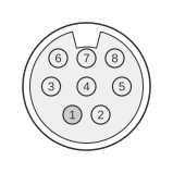 8 pin mini-DIN male connector to the computer
 25 pin D-SUB male connector to the modem
Apple Macintosh serial ports use RS-422 balanced differential signalling, governed by ANSI/TIA/EIA-422-B, and are controlled by the Zilog Z8530 Serial Communications Controller. Starting with the Macintosh Plus (1986), Apple replaced the earlier DE-9 connector with a mini-DIN-8 on both the modem port (telephone icon) and printer port (printer icon), which are electrically identical. This cable adapts the Mac’s mini-DIN-8 modem port to a DB-25 male DCE connector in RS-232-compatible mode, using only the unbalanced (−) data lines and omitting DTR assertion; RxD+ (pin 8) is tied to GND (pin 4) to correctly bias the differential receiver.
| Signal | mini-DIN8 Pin | Dir | DB 25 Pin | Signal |
|---|---|---|---|---|
| HSKo | 1 | OUT | 4 | RTS |
| HSKi | 2 | IN | 5 | CTS |
| TxD- | 3 | OUT | 2 | TxD |
| RxD- | 5 | IN | 3 | RxD |
| GND+RxD+ | 4+8 | - | 7 | GND |
| 6+20 | DSR+DTR |
Signals
- HSKo — Handshake output from the Mac; wired to the Z8530 DTR pin internally. Connected here to DB-25 pin 4 (RTS) to assert RTS to the modem.
- HSKi — Handshake input to the Mac; can function as DSR or an external clock input. Connected here to DB-25 pin 5 (CTS).
- TxD− — Transmit data, negative leg of the RS-422 balanced pair. In RS-232-compatible mode this carries the unbalanced transmit signal to DB-25 pin 2.
- RxD− — Receive data, negative leg of the RS-422 balanced pair. In RS-232-compatible mode this carries the unbalanced receive signal from DB-25 pin 3.
- GND+RxD+ — Mini-DIN-8 pin 4 (signal ground) and pin 8 (RxD+, the positive receive leg) are tied together and connected to DB-25 pin 7 (GND). Grounding RxD+ biases the differential input so that RxD− operates as a single-ended RS-232-compatible input.
- DSR+DTR — DB-25 pins 6 (DSR) and 20 (DTR) are looped together on the modem side. DTR is not driven from the Mac in this configuration; looping DSR to DTR keeps the modem active without Mac-side DTR assertion.
Notes
- The mini-DIN-8 connector on the Mac is keyed and cannot be inserted in the wrong orientation.
- Both the modem port and printer port on the Mac are electrically identical RS-422 interfaces; either may be used with this cable.
- RS-422 electrical parameters: differential driver output ≥ ±2 V across 100 Ω load; receiver sensitivity ±200 mV; common-mode range −7 V to +7 V.
- Throughput is limited by the host CPU: approximately 19.2 kbps on 68000-based Macs, up to 57.6 kbps on 68020/030 models, and up to 115.2 kbps on 68040-based machines.
- For cables that assert DTR, a separate Phase I or Phase II modem cable configuration is used, as documented in Apple’s Inside Macintosh: Devices — Serial Driver.