
The USB 2.0 cable carries four conductors on a fixed pin assignment defined by the USB Implementers Forum specification (Revision 2.0, April 2000). It supports Low-Speed (1.5 Mbit/s), Full-Speed (12 Mbit/s), and High-Speed (480 Mbit/s) operation, with a maximum cable segment length of 5 m for High-Speed devices (limited by the maximum round-trip signal delay of approximately 1.5 µs). The same four-signal assignment applies to Standard Type-A, Type-B, Mini-A, and Mini-B connectors; Mini-USB and Micro-USB variants add a fifth ID pin not present in this generic schematic.
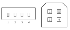 4 pin USB A / USB B / mini-USB jack connector
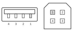 4 pin USB A or USB B plug connector
| Pin one side | Signal | Description | Pin other side |
|---|---|---|---|
| 1 | USB Vcc (Vbus) | usually RED, wire should be 20-28 AWG | 1 |
| 2 | USB Data - | usually WHITE, wire should be 28 AWG | 2 |
| 3 | USB Data + | usually GREEN, wire should be 28 AWG | 3 |
| 4 | GND | usually BLACK, wire should be 20-28 AWG | 4 |
Notes
- USB D+ and D− are twisted together as a pair inside the cable. The outer shell comprises copper braid and aluminium foil shielding.
- VBUS and GND conductors use 20–28 AWG wire; D+ and D− conductors use 28 AWG wire.
- Maximum cable segment length is 5 m for High-Speed (480 Mbit/s) operation. Longer runs require an active USB hub or repeater.
- VBUS supplies +5 V (nominally) to bus-powered devices. The host or hub is responsible for current limiting per the USB specification.
Signals
- VBUS — +5 V bus power; red wire; 20–28 AWG; supplies up to 500 mA (USB 2.0) to bus-powered devices.
- D− — Differential data minus; white wire; 28 AWG; twisted with D+ to reduce noise and crosstalk.
- D+ — Differential data plus; green wire; 28 AWG; twisted with D−; also used to signal device speed via pull-up resistor on the device side.
- GND — Signal and power return; black wire; 20–28 AWG.
References
- Universal Serial Bus Specification, Revision 2.0 — USB Implementers Forum, April 2000