
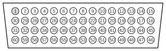
 EIA/TIA-232 DCE Cable Pinout (DB60 to DB25)
The Cisco EIA/TIA-232 DCE cable connects the proprietary 60-pin DB-60 connector on the router’s WAN serial port to a DB-25 connector at the network end, which carries a female receptacle in DCE mode. EIA/TIA-232 (also known as RS-232) is a single-ended, unbalanced serial interface standardised by ANSI/TIA-232-F, originally used widely for data communication between terminal equipment and modems. In this DCE configuration, the Cisco router supplies the clocking signals to the attached DTE device, and the signal directions on the DB-60 side are inverted relative to the DTE variant of the same cable. The cable is used on Cisco 4000, 4500, 4700, 7000, AGS+, 2500, and 3000 series routers equipped with a Four-Port or Dual Serial WAN module; the Cisco part numbers are CAB-232FC (female/DCE) for the standard variant.
| 60 Pin1 | Signal | Description | Direction | 25 Pin | Signal |
|---|---|---|---|---|---|
| J1-50 J1-51 | MODE_0 GND | Shorting group | - | - | - |
| J1-46 | Shield GND | Single | - | J2-1 | Shield GND |
| J1-36 Shield | RxD/TxD - | Twisted pair no. 9 | ← - | J2-2 Shield | TxD - |
| J1-41 Shield | TxD/RxD - | Twisted pair no. 5 | → - | J2-3 Shield | RxD - |
| J1-35 Shield | CTS/RTS - | Twisted pair no. 10 | ← - | J2-4 Shield | RTS - |
| J1-42 Shield | RTS/CTS - | Twisted pair no. 4 | → - | J2-5 Shield | CTS - |
| J1-43 Shield | DTR/DSR - | Twisted pair no. 3 | → - | J2-6 Shield | DSR - |
| J1-45 Shield | Circuit GND - | Twisted pair no. 1 | - - | J2-7 Shield | Circuit GND |
| J1-44 Shield | LL/DCD - | Twisted pair no. 2 | → - | J2-8 Shield | DCD - |
| J1-39 Shield | TxCE/TxC - | Twisted pair no. 7 | → - | J2-15 Shield | TxC - |
| J1-40 Shield | NIL/RxC - | Twisted pair no. 6 | → - | J2-17 Shield | RxC - |
| J1-33 Shield | DCD/LL - | Twisted pair no. 12 | ← - | J2-18 Shield | LTST - |
| J1-34 Shield | DSR/DTR - | Twisted pair no. 11 | <- - | J2-20 Shield | DTR - |
| J1-38 Shield | RxC/TxCE - | Twisted pair no. 8 | ← - | J2-24 Shield | TxCE - |
Notes
- Arrows indicate signal direction: → indicates DTE to DCE, and ← indicates DCE to DTE.
- (1) Any pin not referenced is not connected.
- The DB-60 connector is a proprietary Cisco high-density 60-pin interface; the interface type and DTE/DCE mode are selected by shorting specific MODE pins on the DB-60 (J1-50/J1-51 shorting group shown above selects EIA/TIA-232 mode).
- In DCE mode the Cisco router supplies transmit clock (TxC, TxCE) and receive clock (RxC) to the attached DTE device; the clocking rows in the table above reflect this direction.
- EIA/TIA-232 uses single-ended (unbalanced) signalling at ±3 V to ±15 V; the standard specifies a maximum data rate of 20 kbit/s over cable lengths up to 15 m, though the interface is commonly operated at higher rates over short distances.
- The network end of the DCE cable carries a female DB-25 receptacle (FCE); DTE cables carry a male DB-25 plug (MT suffix).
Signals
- MODE_0 / GND — shorting group on J1-50/J1-51 that selects EIA/TIA-232 interface type on the DB-60 port; not connected to the network end
- Shield / GND — chassis ground and cable shield, tied at J1-46 to DB-25 pin 1
- RxD / TxD — receive data (DCE←DTE); DB-60 J1-36 maps to DB-25 J2-2 (TxD from DTE perspective); signal directions are labelled from the DCE (router) viewpoint
- TxD / RxD — transmit data (DCE→DTE); DB-60 J1-41 maps to DB-25 J2-3 (RxD from DTE perspective)
- CTS / RTS — clear to send (DCE→DTE); DB-60 J1-35 maps to DB-25 J2-4 (RTS from DTE perspective)
- RTS / CTS — request to send (DCE←DTE); DB-60 J1-42 maps to DB-25 J2-5 (CTS from DTE perspective)
- DTR / DSR — data terminal ready from DTE, presented as DSR to the network end; DB-60 J1-43 maps to DB-25 J2-6
- Circuit GND — signal ground (reference); DB-60 J1-45 maps to DB-25 J2-7
- LL / DCD — local loop / data carrier detect; DB-60 J1-44 maps to DB-25 J2-8
- TxCE / TxC — transmit clock external (DCE-supplied); DB-60 J1-39 maps to DB-25 J2-15
- NIL / RxC — receive clock (DCE-supplied); DB-60 J1-40 maps to DB-25 J2-17
- DCD / LL — data carrier detect / local loop; DB-60 J1-33 maps to DB-25 J2-18 (LTST — local test)
- DSR / DTR — data set ready (DCE→DTE); DB-60 J1-34 maps to DB-25 J2-20 (DTR from DTE perspective)
- RxC / TxCE — receive clock / transmit clock external; DB-60 J1-38 maps to DB-25 J2-24