
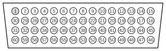
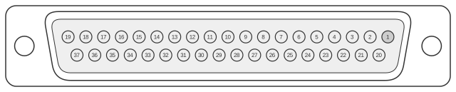
 EIA/TIA-449 DCE Cable Pinout (DB60 to DB37)
EIA/TIA-449 (also known as RS-449) is a high-performance serial interface standard using a 37-pin D-sub (DB-37) connector, designed as a successor to RS-232 and supporting balanced differential signalling per RS-422 for primary data signals and RS-423 for control signals, with a maximum throughput of 10 Mbps. Cisco routers in the 4000, 4500, and 4700 series use a 60-pin high-density DB-60 connector on the router end of all WAN serial cables, with the interface type and DTE/DCE mode selected by shorting pins on the DB-60. The DCE variant of this cable (Cisco part CAB-449FC) carries a female DB-37 receptacle at the network end, indicating that the Cisco router acts as the DCE and supplies the clock signal to the attached DTE device. EIA/TIA-449 has largely been superseded in practice by EIA/TIA-530, which carries the same RS-422 electrical characteristics in a more compact DB-25 housing.
| 60 Pin1 | Signal | Description | Direction | 37 Pin | Signal |
|---|---|---|---|---|---|
| J1-49 J1-48 | MODE_1 GND | Shorting group | - | - | - |
| J1-46 | Shield_GND | Single | - | J2-1 | Shield GND |
| J1-28 J1-27 | RxD/TxD+ RxD/TxD- | Twisted pair no. 11 | ← ← | J2-4 J2-22 | SD+ SD- |
| J1-13 J1-14 | TxCE/TxC+ TxCE/TxC- | Twisted pair no. 7 | → → | J2-5 J2-23 | ST+ ST- |
| J1-11 J1-12 | TxD/RxD+ TxD/RxD- | Twisted pair no. 6 | → → | J2-6 J2-24 | RD+ RD- |
| J1-1 J1-2 | CTS/RTS+ CTS/RTS- | Twisted pair no. 1 | ← ← | J2-7 J2-25 | RS+ RS- |
| J1-24 J1-23 | TxC/RxC+ TxC/RxC- | Twisted pair no. 9 | → → | J2-8 J2-26 | RT+ RT- |
| J1-9 J1-10 | RTS/CTS+ RTS/CTS- | Twisted pair no. 5 | → → | J2-9 J2-27 | CS+ CS- |
| J1-29 J1-30 | NIL/LL Circuit_GND | Twisted pair no. 12 | → - | J2-10 J2-37 | LL SC |
| J1-7 J1-8 | DTR/DSR+ DTR/DSR- | Twisted pair no. 4 | → → | J2-11 J2-29 | DM+ DM- |
| J1-3 J1-4 | DSR/DTR+ DSR/DTR- | Twisted pair no. 2 | ← ← | J2-12 J2-30 | TR+ TR- |
| J1-5 J1-6 | DCD/DCD+ DCD/DCD- | Twisted pair no. 3 | → → | J2-13 J2-31 | RR+ RR- |
| J1-26 J1-25 | RxC/TxCE+ RxC/TxCE- | Twisted pair no. 10 | ← ← | J2-17 J2-35 | TT+ TT- |
| J1-15 J1-16 | Circuit_GND Circuit_GND | Twisted pair no. 8 | - - | J2-19 J2-20 | SG RC |
Notes
- Arrows indicate signal direction: → indicates DTE to DCE, and ← indicates DCE to DTE.
- (1) Any pin not referenced is not connected.
- The DB-60 connector on the Cisco router end uses shorting pins (MODE_1/GND group, pins J1-48/J1-49) to select the EIA/TIA-449 interface type; other mode pins in the J1-46 to J1-56 range select DTE or DCE operation.
- The female DB-37 receptacle at the network end identifies this as the DCE cable; the Cisco router therefore supplies transmit and receive clocking (ST and RT signals) to the attached DTE equipment.
- Primary data signals (SD, RD, RS, CS, DM, TR, RR, TT, and timing) use RS-422 balanced differential pairs; the local loop-back (LL) control line uses RS-423 single-ended signalling.
- EIA/TIA-449 signal names differ from their RS-232 equivalents: SD (Send Data) corresponds to TxD, RD (Receive Data) to RxD, RS (Request to Send) to RTS, CS (Clear to Send) to CTS, DM (Data Mode) to DSR, TR (Terminal Ready) to DTR, RR (Receiver Ready) to DCD, and SG (Signal Ground) to circuit ground.
Signals
- SD+/SD- — Send Data (positive/negative): balanced data transmitted from the DTE to the DCE; maps to DB-60 pins J1-28/J1-27 and DB-37 pins J2-4/J2-22.
- ST+/ST- — Send Timing (positive/negative): transmit clock provided by the DCE to the DTE; maps to DB-60 pins J1-13/J1-14 and DB-37 pins J2-5/J2-23.
- RD+/RD- — Receive Data (positive/negative): balanced data transmitted from the DCE to the DTE; maps to DB-60 pins J1-11/J1-12 and DB-37 pins J2-6/J2-24.
- RS+/RS- — Request to Send (positive/negative): handshake signal from the DTE requesting permission to transmit; maps to DB-60 pins J1-1/J1-2 and DB-37 pins J2-7/J2-25.
- RT+/RT- — Receive Timing (positive/negative): receive clock provided by the DCE; maps to DB-60 pins J1-24/J1-23 and DB-37 pins J2-8/J2-26.
- CS+/CS- — Clear to Send (positive/negative): handshake signal from the DCE granting permission to transmit; maps to DB-60 pins J1-9/J1-10 and DB-37 pins J2-9/J2-27.
- LL — Local Loopback: single-ended control signal that instructs the DCE to loop the transmitted signal back to the DTE for testing; maps to DB-60 pin J1-29 and DB-37 pin J2-10.
- SC — Signal Ground return for the LL circuit; maps to DB-60 pin J1-30 and DB-37 pin J2-37.
- DM+/DM- — Data Mode (positive/negative): indicates the DCE is ready for data operation (equivalent to DSR); maps to DB-60 pins J1-7/J1-8 and DB-37 pins J2-11/J2-29.
- TR+/TR- — Terminal Ready (positive/negative): indicates the DTE is ready (equivalent to DTR); maps to DB-60 pins J1-3/J1-4 and DB-37 pins J2-12/J2-30.
- RR+/RR- — Receiver Ready (positive/negative): indicates the DCE is detecting a valid carrier (equivalent to DCD); maps to DB-60 pins J1-5/J1-6 and DB-37 pins J2-13/J2-31.
- TT+/TT- — Terminal Timing (positive/negative): optional external transmit clock sourced by the DTE; maps to DB-60 pins J1-26/J1-25 and DB-37 pins J2-17/J2-35.
- SG — Signal Ground: circuit reference ground; maps to DB-60 pin J1-15 and DB-37 pin J2-19.
- RC — Receive Common: common return for receive signals; maps to DB-60 pin J1-16 and DB-37 pin J2-20.
- Shield_GND — Shield/Frame Ground: protective earth connection; maps to DB-60 pin J1-46 and DB-37 pin J2-1.
- MODE_1/GND — DB-60 shorting group that selects EIA/TIA-449 interface type on the router; not connected at the DB-37 end.