
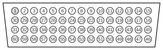
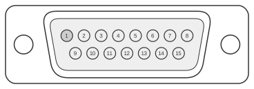
 X.21 DTE Cable Pinout (DB-60 to DB-15)
ITU-T X.21 is a fully balanced differential serial interface defined in ITU-T X.21 (1992) using a 15-pin D-sub (DB-15) connector at the network end. It employs V.11 electrical characteristics throughout, supporting a maximum throughput of 10 Mbps and offering good EMI resistance compared with single-ended alternatives. The Cisco X.21 DTE cable (part number CAB-X21MT) connects the 60-pin high-density DB-60 router port — used across the Cisco 4000, 4500, and 4700 series — to a male DB-15 plug at the DCE network end. The interface type and DTE mode are selected by shorting specific pins on the DB-60 connector; the physical cable determines which of the five supported serial standards is active.
| 60 Pin1 | Signal | Description | Direction | 15 Pin | Signal |
|---|---|---|---|---|---|
| J1-48 J1-47 | GND MODE_2 | Shorting group | - | - | - |
| J1-51 J1-52 | GND MODE_DCE | Shorting group | - | - | - |
| J1-46 | Shield_GND | Single | - | J2-1 | Shield GND |
| J1-11 J1-12 | TxD/RxD+ TxD/RxD- | Twisted pair no. 3 | → → | J2-2 J2-9 | Transmit+ Transmit- |
| J1-9 J1-10 | RTS/CTS+ RTS/CTS- | Twisted pair no. 2 | → → | J2-3 J2-10 | Control+ Control- |
| J1-28 J1-27 | RxD/TxD+ RxD/TxD- | Twisted pair no. 6 | ← ← | J2-4 J2-11 | Receive+ Receive- |
| J1-1 J1-2 | CTS/RTS+ CTS/RTS- | Twisted pair no. 1 | ← ← | J2-5 J2-12 | Indication+ Indication- |
| J1-26 J1-25 | RxC/TxCE+ RxC/TxCE- | Twisted pair no. 5 | ← ← | J2-6 J2-13 | Timing+ Timing- |
| J1-15 Shield | Control_GND - | Twisted pair no. 4 | - - | J2-8 Shield | Control GND - |
Notes
- Arrows indicate signal direction: → indicates DTE to DCE, and ← indicates DCE to DTE.
- (1) Any pin not referenced is not connected.
- The DB-60 shorting pins J1-48/J1-47 (GND/MODE_2) and J1-51/J1-52 (GND/MODE_DCE) select the X.21 interface type on the router port; these pins carry no data signals to the DB-15 end.
- The DTE cable (CAB-X21MT) carries a male DB-15 plug at the network end. The corresponding DCE cable (CAB-X21FC) carries a female DB-15 receptacle; the DCE device supplies the clock signal.
- All data and timing signals are differential (balanced) per V.11; the cable uses five twisted pairs for Transmit, Control, Receive, Indication, and Timing circuits.
- Pin J2-8 on the DB-15 carries Signal Ground (combined Control GND); pin J2-1 is Shield Ground.
Signals
- Shield GND — chassis/shield earth connection; DB-60 J1-46 to DB-15 J2-1.
- Transmit+ / Transmit− — DTE-to-DCE data circuit (balanced pair); DB-60 J1-11/J1-12 to DB-15 J2-2/J2-9.
- Control+ / Control− — DTE-to-DCE control circuit, equivalent to the RTS function in X.21 signalling; DB-60 J1-9/J1-10 to DB-15 J2-3/J2-10.
- Receive+ / Receive− — DCE-to-DTE data circuit (balanced pair); DB-60 J1-28/J1-27 to DB-15 J2-4/J2-11.
- Indication+ / Indication− — DCE-to-DTE indication circuit, equivalent to the CTS/DCD function; DB-60 J1-1/J1-2 to DB-15 J2-5/J2-12.
- Timing+ / Timing− — DCE-to-DTE signal timing clock; DB-60 J1-26/J1-25 to DB-15 J2-6/J2-13.
- Control GND / Shield — signal ground reference for the Control pair; DB-60 J1-15/Shield to DB-15 J2-8/Shield.
- GND / MODE_2 — DB-60 shorting pair (J1-48/J1-47) that selects X.21 interface mode; not connected to DB-15.
- GND / MODE_DCE — DB-60 shorting pair (J1-51/J1-52) that asserts DTE mode; not connected to DB-15.