
The V.35 crossover cable connects two devices that present the same role — either two DCE ports or two DTE ports — back-to-back using the 34-pin ISO 2593 (MRAC-34) Winchester connector. V.35 uses hybrid signalling: V.11 balanced differential pairs for data and clock circuits, and V.28 unbalanced single-ended signals for modem control lines. The ITU-T V.35 recommendation was published in October 1984 and subsequently withdrawn, yet the interface remains a widely used de facto standard for synchronous WAN links operating at rates from 64 kbit/s up to several megabits per second. The crossover swaps the Send Data, Receive Data, and associated clock pairs between the two ends so that each device’s transmit circuits drive the other’s receive circuits.
 34 pin M/34 male connector to the DCE
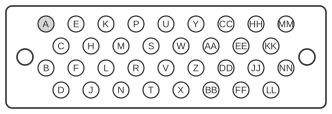 34 pin M/34 female connector to the DCE
| DTE (34-pin Winchester) | DCE (34-pin Winchester) | Notes |
|---|---|---|
| A | A | |
| B | B | |
| C | F | |
| E | H | |
| F | C | |
| H | E | |
| P | R | inside twisted pair with S wire |
| R | P | inside twisted pair with T wire |
| S | T | inside twisted pair with P wire |
| T | S | inside twisted pair with R wire |
| U | V | inside twisted pair with W wire |
| V | U | inside twisted pair with X wire |
| W | X | inside twisted pair with U wire |
| X | W | inside twisted pair with V wire |
| Y | BB | |
| Z | AA | |
| AA | Z | |
| BB | Y |
Notes
The Winchester ISO 2593 connector uses lettered pin designations (A, B, C, E, F, H, P, R, S, T, U, V, W, X, Y, Z, AA, BB, etc.) rather than numeric ones. The differential data and clock pairs are physically arranged as twisted pairs within the cable: P/S, R/T, U/W, and V/X travel as pairs, so the crossover must preserve these pairings. Ground and shield pins A and B connect straight through. Control signals C, E, F, and H carry the unbalanced V.28 modem control lines and are crossed between their functional equivalents. Y/BB and Z/AA form the transmit and receive clock pairs on the second connector.
Signals
- A — Signal ground (straight through)
- B — Signal ground (straight through)
- C — Request to Send (RTS); crossed with F
- E — Data Set Ready (DSR) / Data Carrier Detect; crossed with H
- F — Clear to Send (CTS); crossed with C
- H — Data Terminal Ready (DTR); crossed with E
- P — Send Data positive (SD+); crossed with R, twisted pair with S
- R — Receive Data positive (RD+); crossed with P, twisted pair with T
- S — Send Data negative (SD−); crossed with T, twisted pair with P
- T — Receive Data negative (RD−); crossed with S, twisted pair with R
- U — Send Timing positive (SCTE+); crossed with V, twisted pair with W
- V — Receive Timing positive (SCR+); crossed with U, twisted pair with X
- W — Send Timing negative (SCTE−); crossed with X, twisted pair with U
- X — Receive Timing negative (SCR−); crossed with W, twisted pair with V
- Y — Send Clock positive (SCT+); crossed with BB
- Z — Send Clock negative (SCT−); crossed with AA
- AA — Receive Clock negative (SCR−); crossed with Z
- BB — Receive Clock positive (SCR+); crossed with Y
References
- ITU-T Recommendation V.35 (1984) — Data transmission at 48 kilobits per second using 60–108 kHz group band circuits (International Telecommunication Union; later withdrawn)
- ISO 2593 — Connector pin allocations for use with high-speed data terminal equipment (International Organization for Standardization)