
The Cisco DB-60 is a 60-pin high-density connector used on the router end of all classic Cisco WAN serial cables on the 4000, 4500, and 4700 series, supporting EIA/TIA-232, EIA/TIA-449, EIA/TIA-530, ITU-T V.35, and ITU-T X.21 signalling standards through cable swapping alone. This back-to-back cable connects two such routers directly without intervening network equipment, wired in X.21 format so that one router presents as DCE and the other as DTE. The differential signal pairs — transmit, receive, control, and clock — are crossed between the two DB-60 connectors to complete the DTE–DCE handshake. Mode-selection shorting pins on the DB-60 (MODE_0, MODE_DCE, and related) must be set appropriately at each end to activate X.21 mode and assign the correct DTE or DCE role.
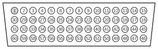 60 pin Cisco DB connector to the Serial Port on Cisco Router
60 pin Cisco DB connector to the Serial Port on Cisco Router
| Serial Port on Cisco Router Pin Name | Serial Port on Cisco Router Pin Number | Direction | Serial Port on Cisco Router Pin Number | Serial Port on Cisco Router Pin Name | Description |
|---|---|---|---|---|---|
| Ground | 46 | ↔ | 46 | Ground | Shield Ground |
| TXD/RXD+ | 11 | → | 28 | RXD/TXD+ | Twisted Pair No.3 |
| TXD/RXD- | 12 | → | 27 | RXD/TXD- | Twisted Pair No.3 |
| RTS/CTS+ | 9 | → | 1 | CTS/RTS+ | Twisted Pair No.2 |
| RTS/CTS- | 10 | → | 2 | CTS/RTS- | Twisted Pair No.2 |
| RXD/TXD+ | 28 | ← | 11 | TXD/RXD+ | Twisted Pair No.4 |
| RXD/TXD- | 27 | ← | 12 | TXD/RXD- | Twisted Pair No.4 |
| CTS/RTS+ | 1 | ← | 9 | RTS/CTS+ | Twisted Pair No.1 |
| CTS/RTS- | 2 | ← | 10 | RTS/CTS- | Twisted Pair No.1 |
| RXC/TXCE+ | 26 | ← | 24 | TXC/RXC+ | Twisted Pair No.5 |
| RXC/TXCE- | 25 | ← | 23 | TXC/RXC- | Twisted Pair No.5 |
| Ground | 15 | ↔ | 15 | Ground | Circuit Ground |
| To Local 47 | 48 | 48 | To Local 47 | Ground Mode 2 | |
| To Local 48 | 47 | 47 | To Local 48 | Ground Mode 2 | |
| To Local 52 | 51 | Ground Mode DCE | |||
| To Local 51 | 52 | Ground Mode DCE | |||
| Not Used | 16 | 16 | Not Used | Not Used |
Notes
- The DCE-side wiring requires two additional wires on pins 25 and 26 (RXC/TXCE differential pair) that are not present in a standard Cisco X.21 DTE cable; most other signal pairs are swapped between the two connectors.
- All differential signal pairs use balanced V.11 (RS-422) electrical characteristics, consistent with the X.21 interface standard.
- Mode pins on the DB-60 connector (pins 47–52 range) select the interface type and DTE/DCE role; shorting pin 51 to ground activates DCE mode on the appropriate router end.
Signals
- Ground (pin 46) — Shield ground, common to both connectors.
- TXD/RXD+ (pin 11) / RXD/TXD+ (pin 28) — Positive leg of the transmit/receive differential data pair (Twisted Pair No. 3); crossed so that the transmit output of one router drives the receive input of the other.
- TXD/RXD− (pin 12) / RXD/TXD− (pin 27) — Negative leg of the same transmit/receive data pair (Twisted Pair No. 3).
- RTS/CTS+ (pin 9) / CTS/RTS+ (pin 1) — Positive leg of the control signal pair (Twisted Pair No. 2), corresponding to the X.21 Control/Indication circuit; crossed between DTE and DCE ends.
- RTS/CTS− (pin 10) / CTS/RTS− (pin 2) — Negative leg of the control pair (Twisted Pair No. 2).
- RXC/TXCE+ (pin 26) / TXC/RXC+ (pin 24) — Positive leg of the receive/transmit clock pair (Twisted Pair No. 5); carries the X.21 Signal Timing circuit; crossed so DCE clock drives DTE clock input.
- RXC/TXCE− (pin 25) / TXC/RXC− (pin 23) — Negative leg of the clock pair (Twisted Pair No. 5).
- Ground (pin 15) — Circuit ground, common to both connectors.
- Pins 47, 48 — Mode selection shorting pins (Ground Mode 2); shorted locally on each connector to configure the interface mode.
- Pins 51, 52 — Mode selection shorting pins (Ground Mode DCE); shorted locally on the DCE-side connector only to assert DCE role.
- Pin 16 — Not used on either end.