
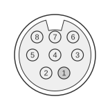
 8 pin mini-DIN female connector at the computer.
The SGI mini-DIN-8 female serial port is found on Silicon Graphics Personal IRIS 4D/30, 4D/35, Indigo, Indy, and Indigo2 workstations from the late 1980s through the mid-1990s. The port supports two software-selectable operating modes: a 4D-compatible (EIA-232 unbalanced) mode and a Macintosh SE-compatible (EIA-422 differential) mode, making it electrically and mechanically interchangeable with the Apple Macintosh mini-DIN-8 connector. Signal voltages vary by model: the Indigo operates at ±5 V (EIA-423), whilst the Indy and Indigo2 use ±9 V for improved noise immunity.
| Pin | Name | Dir | Description |
|---|---|---|---|
| 1 | DTR | OUT | Data Terminal Ready |
| 2 | CTS | IN | Clear to Send |
| 3 | TXD | OUT | Transmit Data |
| 4 | GND | - | System Ground |
| 5 | RXD | IN | Receive Data |
| 6 | RTS | OUT | Request to Send |
| 7 | CD | IN | Carrier Detect |
| 8 | GND | - | System Ground |
Notes
- The table above shows the 4D-compatible (EIA-232 / EIA-423) mode pin assignments, as documented in the SGI Indy Owner’s Guide (Table A-1) and the SGI Hardware Developer Handbook.
- In EIA-422 (Macintosh SE-compatible) mode, the same physical connector carries a different signal set: Pin 1=HSKo (Handshake output), Pin 2=HSKi or external clock input, Pin 3=TxD− (transmit data, inverted), Pin 4=GND, Pin 5=RxD− (receive data, inverted), Pin 6=TxD+ (transmit data), Pin 7=GPi (general-purpose input), Pin 8=RxD+ (receive data). This mode supports balanced differential signalling suitable for longer cable runs.
- The mode is selected in software (IRIX); no hardware jumper changes are required.
- The SGI mini-DIN-8 is not compatible with standard PC DB-9 or DB-25 serial cables; a dedicated adapter is required.
- Later SGI workstations (Octane, Onyx2, Origin 2000) use a standard IBM PC/AT-compatible DB-9 male connector with a different pinout and are not covered here.
- Maximum transfer rate on these ports is 38,400 baud.
Signals
- DTR — Data Terminal Ready; output from the workstation, asserted when the host is ready to communicate.
- CTS — Clear to Send; input to the workstation, asserted by the remote device to permit transmission.
- TXD — Transmit Data; serial data output from the workstation to the remote device.
- GND — System Ground; pins 4 and 8 are both signal ground returns.
- RXD — Receive Data; serial data input to the workstation from the remote device.
- RTS — Request to Send; output from the workstation, requesting permission to transmit.
- CD — Carrier Detect (DCD); input to the workstation, asserted by a modem when a carrier signal is detected.
References
- SGI Indy Workstation Owner’s Guide (Doc. 007-9804-060), Appendix A: Cable Pinout Assignments — Silicon Graphics, Inc.
- Getting 422 In and Out of Your SGI – Lurker’s Guide — lurkertech.com