
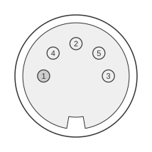
 Apple IIc Printer/Modem port - 5 Pin DIN female connector
The Apple IIc (1984) provides two identical 5-pin DIN female serial ports — Port 1 (printer) and Port 2 (modem/communication) — using RS-232-C compatible single-ended signalling rather than the RS-422 differential signalling found on later Apple products. Both ports share the same physical connector and pin assignments; they are distinguished only by their default baud rates and their logical slot assignments in the firmware. The ports are described in detail in Chapter 7 and Chapter 8 of the Apple IIc Technical Reference Manual (1985), with hardware connector diagrams and signal tables in Chapter 11.
| Pin | Signal | Name | Notes |
|---|---|---|---|
| 1 | DTR | Data Terminal Ready | becomes active when the IIc is ready to go on line |
| 2 | TD | Transmit Data | conveys serial data sent from the IIc |
| 3 | SG | Signal Ground | is used to provide a common ground reference for the electronics in both the IIc and the device it is connected to |
| 4 | RD | Receive Data | receives serial data sent from the device to the IIc it is connected to |
| 5 | DSR | Data Set Ready | is asserted by the device the IIc is connected to when it is ready to go on line |
Notes
- Both serial ports on the Apple IIc use identical 5-pin DIN female connectors with the same pin assignments. The principal difference is the default configuration: Port 1 (printer) defaults to 9600 baud and appears to firmware as slot 1; Port 2 (modem/communication) defaults to 300 baud and appears as slot 2.
- The signalling is RS-232-C compatible (single-ended), unlike the RS-422 differential signalling used on the later Apple IIc Plus, Apple IIgs, and Macintosh series. This distinction matters when selecting cables and adaptors.
- Port configurations can be changed via keyboard commands or the Apple IIc System Utilities disk; they are not set by DIP switches.
- The RS-232 device firmware entry point is at ROM page $C1 (printer); the communication device is at ROM page $C2 (modem).
Signals
- DTR — Data Terminal Ready; driven by the IIc, asserted when the computer is ready to communicate; used as the hardware flow control output (hardware DTR handshake protocol on Port 1).
- TD — Transmit Data; serial data output from the IIc to the connected device.
- SG — Signal Ground; common reference ground for both the IIc and the connected device.
- RD — Receive Data; serial data input to the IIc from the connected device.
- DSR — Data Set Ready; driven by the connected device, asserted when the peripheral is ready to communicate.
Default startup configuration (Port 1 — printer)
- 9600 baud
- 8 data bits, no parity
- 2 stop bits
- 80 characters per line
- LF after CR
- Command character: CTRL-I
- Hardware (DTR flow control) handshake
Default startup configuration (Port 2 — modem/communication)
- 300 baud
- 8 data bits, no parity
- 1 stop bit
- No LF after CR
- Command character: CTRL-A
References
- Apple IIc Technical Reference Manual — Apple Computer, Inc., 1985
- Apple Technical Procedures Peripheral Interface Guide (PN 072-0213D) — Apple Computer, Inc., March 1989