
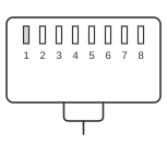
 RJ-45 8pin male connector
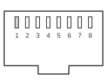 RJ-45 8pin female connector
The EIA/TIA-561 standard, approved on 20 March 1990, defines a non-synchronous RS-232 serial interface using an 8-position modular (RJ-45) connector. It references EIA/TIA-562 for its electrical characteristics rather than RS-232-F directly, permitting operation at the lower supply voltages common in office and portable equipment. The interface carries the standard DTE-to-DCE signal set — transmit and receive data, handshaking lines, and modem-status indicators — across a compact modular jack. Although often labelled “RS-232D over RJ-45”, the governing specification is EIA/TIA-561; numerous vendor implementations (including Cisco console cables) use non-standard pin assignments that differ from the specification.
| Pin | Name | Dir | Description |
|---|---|---|---|
| 1 | DSR / RI | IN | Data Set Ready / Ring Indicator |
| 2 | CD | IN | Carrier Detect |
| 3 | DTR | OUT | Data Terminal Ready |
| 4 | GND | System Ground | |
| 5 | RXD | IN | Receive Data |
| 6 | TXD | OUT | Transmit Data |
| 7 | CTS | IN | Clear to Send |
| 8 | RTS | OUT | Request to Send |
Signals
- RI — Ring Indicator (V.24 circuit 125); signals that the DCE is receiving a ringing signal on the telephone line. EIA/TIA-561 assigns this signal to pin 1 alone; some vendor implementations tie DSR here as well, but the standard specifies RI only. The equivalent cross-connect on a DE-9 is pin 9.
- CD — Carrier Detect (Received Line Signal Detector, V.24 circuit 109); asserted by the DCE when it has detected a carrier from the remote modem.
- DTR — Data Terminal Ready (V.24 circuit 108); asserted by the DTE to signal that it is ready to communicate and to maintain a connection.
- GND — Signal Ground (V.24 circuit 102); common reference for all signal voltages.
- RXD — Received Data (V.24 circuit 104); serial data stream from DCE to DTE.
- TXD — Transmitted Data (V.24 circuit 103); serial data stream from DTE to DCE.
- CTS — Clear to Send (V.24 circuit 106); asserted by the DCE to indicate that the DTE may begin transmitting.
- RTS — Request to Send (V.24 circuit 105); asserted by the DTE to request permission to transmit.
Notes
- Direction is DTE (Computer) relative to DCE (Modem).
- EIA/TIA-561 references EIA/TIA-562 for electrical levels: minimum driver output (loaded, 3 kΩ) ≥ 3.7 V; receiver thresholds ±3 V; maximum capacitive load 1000 pF — implying shorter maximum cable lengths than RS-232-F’s 2500 pF limit.
- Pin 1 is specified as RI (Ring Indicator) by EIA/TIA-561. Some implementations route DSR to pin 1 instead of or alongside RI; this is a vendor practice, not the standard assignment.
- Many vendor console-cable pin assignments (e.g., Cisco) differ from the EIA/TIA-561 standard; always verify the specific equipment’s documentation before making cables.