
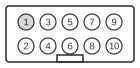
 10 pin IDC male connector at the Serial card.
The DEC DLV11-J (board designation M8043) is a four-channel asynchronous serial module introduced in 1978 for Q-bus and LSI-11 (PDP-11) systems. Each of the four channels presents an independent 10-pin IDC (Berg/AMP) header rather than a DB-25 socket directly on the card. The board supports EIA RS-232C/RS-423 by factory default (both standards simultaneously), EIA RS-422 differential operation with appropriate termination resistors, and 20 mA current-loop operation via the optional DLV11-KA accessory. Nine crystal-controlled baud rates are available (150 to 38400 bps), with 110 bps also supported when the DLV11-KA is fitted.
| Pin | Name | Dir | Description |
|---|---|---|---|
| 1 | CLK | ? | Clock |
| 2 | GND | - | Ground |
| 3 | TXD+ | OUT | Transmit data + |
| 4 | TXD- | OUT | Transmit data - (0V for RS-232, Reader enable for 20mA) |
| 5 | GND | - | Ground |
| 6 | n/c | - | Not connected (no pin) |
| 7 | RXD- | IN | Receive data - |
| 8 | RXD+ | IN | Receive data + |
| 9 | GND | - | Ground |
| 10 | +12V | OUT | +12 VDC |
Signals
- CLK — baud-rate clock input (pin 1); direction is listed as unknown in original documentation and is not a Q-bus system clock.
- GND — signal ground (pins 2, 5, and 9); multiple ground pins reduce noise on the differential pairs.
- TXD+ — positive transmit data line; in RS-422 mode this carries the non-inverted differential signal.
- TXD- — negative transmit data return; held at 0 V (signal ground) for RS-232/RS-423 single-ended operation; carries the complementary differential signal in RS-422 mode; functions as Reader Enable in 20 mA current-loop mode.
- n/c — pin 6 is the index or keying position: no pin is physically installed, preventing reversed insertion of the IDC connector.
- RXD- — negative receive data return; must be tied to pin 9 (GND) for RS-232 single-ended operation; carries the complementary differential signal in RS-422 mode.
- RXD+ — positive receive data line.
- +12V — +12 V supply output (pin 10); the board draws approximately 0.15 A at +12 V in addition to 1 A at +5 V.
Notes
- Direction is Serial card relative to other devices.
- Pin 6 (index/key) has no pin installed; this enforces correct cable orientation and prevents damage from reversed insertion.
- For RS-232/RS-423 single-ended operation, pins 7 (RXD−) and 9 (GND) must be tied together in the cable; omitting this connection causes intermittent receive failures.
- RS-422 differential mode requires 100 Ω termination at the receiver end, and slew-rate resistors (22 kΩ to 1 MΩ, value depending on baud rate) must be fitted on the board.
- Standard DEC cables: BC20N-05 (10-pin IDC to DB-25S, local terminal, ~5 ft), BC21B-05 (modem variant), BC20M-50 (DLV11-J to DLV11-J interconnect at 50 ft).
- The transmit+/− pair maps to DB-25 pin 2 (TXD) and the receive+/− pair to DB-25 pin 3 (RXD) for DTE operation via these cables.
- Each channel has four device registers: RCSR (receive control/status), RBUF (receive buffer), XCSR (transmit control/status), and XBUF (transmit buffer).
- Factory default interrupt vector base is 300 (octal); channel 3 may optionally be configured to use console vectors 60/64.