
The console port on Cisco 1000, 1600, 2500, 2600, and 3600 series IOS routers is an EIA/TIA-232 asynchronous serial interface presented on an RJ-45 (8P8C) socket and configured as Data Terminal Equipment (DTE). Introduced during the mid-to-late 1990s, these ports allow out-of-band management via a rollover cable (pins 1↔8, 2↔7, 3↔6, 4↔5) terminated with an RJ-45-to-DB-9 or RJ-45-to-DB-25 adapter. Unlike the auxiliary port on the same routers, the console port uses only six of the eight pins — pins 1 and 8 are not connected — and does not support hardware flow control or modem control. Default serial parameters across all supported platforms are 9600 bps, 8 data bits, no parity, 1 stop bit, and no flow control.
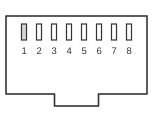 RJ45 FEMALE CONNECTOR at the Cisco routers)
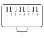 RJ45 MALE CONNECTOR at the cables
| Pin | Name | Description | Dir |
|---|---|---|---|
| 1 | NC | Not Connected | - |
| 2 | DTR | Data Terminal Ready | OUT |
| 3 | TXD | Tranceive Data | OUT |
| 4 | GND | Ground | - |
| 5 | GND | Ground | - |
| 6 | RXD | Receive Data | IN |
| 7 | DSR | Data Set Ready | IN |
| 8 | NC | Not Connected | - |
Signals
- NC — pins 1 and 8 are not connected on the console port RJ-45; the console port does not implement RTS or CTS, and hardware flow control is not supported.
- DTR — Data Terminal Ready; asserted by the router to signal readiness.
- TXD — Transmit Data; serial data sent from the router to the terminal.
- GND — Signal ground; two pins (4 and 5) are tied to ground.
- RXD — Receive Data; serial data received by the router from the terminal.
- DSR — Data Set Ready; indicates modem or terminal readiness (input to the router).
Notes
- The console port is configured as DTE on all 1000, 1600, 2500, 2600, and 3600 series routers; this is the opposite of the DCE role used by the separate Cisco 700-series ISDN routers.
- A flat rollover cable (Cisco part CAB-500RJ=) is required between the router RJ-45 console port and a terminal adapter: pin 1 at one end connects to pin 8 at the other, pin 2 to pin 7, pin 3 to pin 6, and pin 4 to pin 5.
- The RJ-45-to-DB-9 female DTE adapter maps RJ-45 pin 3 (RxD at the adapter input, which is TxD from the router after cable reversal) to DB-9 pin 2, and RJ-45 pin 6 (TxD at the adapter input) to DB-9 pin 3.
- The auxiliary port on the same routers uses the same RJ-45 connector and rollover cable but assigns all eight pins, including RTS on pin 1 and CTS on pin 8, and does support hardware flow control and modem control.
- Do not confuse the console port pinout with the auxiliary port pinout; they share the same physical connector style but differ on pins 1 and 8.