
Available on the three Tandy Color Computer models, also known as the CoCo (or CoCo1), CoCo 2, and CoCo 3.
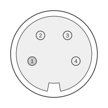 4 PIN DIN 270° FEMALE at the computer.
The Tandy TRS-80 Color Computer serial/printer port is a 4-pin DIN connector introduced in 1981 that provides a true RS-232 interface via dedicated level-converter ICs (U14 and U15), delivering a proper ±12 V signal swing rather than raw TTL levels. Only four signals are exposed — carrier detect, receive data, ground, and transmit data — making it a minimal but standards-compliant RS-232 port. Baud rate and framing are controlled entirely in software, which is why users and programmers came to know it as the “bit-banger” port; the default BASIC configuration runs at 600 baud with 7 data bits and 2 stop bits, though later ROM revisions altered this to 8 data bits. Despite its simplicity, the port saw remarkably diverse use, including serial printers, terminal communications, MIDI adapters, and amateur-radio digital modes.
| Pin | Description as Printer Port | Description as RS-232 * |
|---|---|---|
| 1 | NC - Ignored | CD - Carrier Detect |
| 2 | /READY - High when the printer is ready | DATA IN - RS-232 data |
| 3 | GROUND | GROUND |
| 4 | DATA OUT - RS-232 data | DATA OUT - RS-232 data |
Signals
- CD (Pin 1) — Carrier Detect / general-purpose status input. Hardware constrains this pin as an input only; BASIC printer routines ignore it entirely, whilst communications software may use it as a carrier-detect indicator.
- DATA IN / /READY (Pin 2) — RS-232 receive data input (serial mode) or active-high printer-ready status input (printer mode). Hardware constrains this pin as an input only.
- GROUND (Pin 3) — Signal ground reference.
- DATA OUT (Pin 4) — RS-232 transmit data output (serial mode) or serial data to printer (printer mode). This pin is always an output.
Notes
- The connector is a 4-pin DIN 270° socket mounted at the rear panel of the CoCo (designated P2 in the technical reference manual).
- Although baud rate and framing are software-controlled (“bit-banged”), the voltage levels are true RS-232 (±12 V swing) thanks to the hardware level-converter ICs — not TTL.
- RS-232 logic levels: high (logic 1) above +3 V; low (logic 0) below −3 V; the undefined zone is −3 V to +3 V.
- Default software serial parameters: 600 baud, 1 start bit, 7 data bits (LSB first), 2 stop bits, no parity. Later ROM revisions changed to 8 data bits.
- Pins 1 and 2 are hardware-constrained as inputs; Pin 4 is always an output. This limits the port to half-duplex or simplex serial configurations without additional adapters.
- The port was used by third-party software and hardware adapters for MIDI, amateur-radio digital modes (CW, RTTY), video-digitiser control signals (in conjunction with the joystick port), and external device switching — typically requiring a purpose-built adapter cable.
- Software that needed separate printer and communications functions, or required higher throughput, often added a dedicated hardware UART expansion.
References
- TRS-80 Color Computer Technical Reference Manual (Cat. No. 26-3193) — Radio Shack / Tandy Corporation, 1981