
The 2002 Mitsubishi Lancer (CS3A chassis) with the 2.4 L 4G69 SOHC four-cylinder engine uses a multi-point fuel injection (MFI) engine control unit typical of Mitsubishi’s early-2000s passenger car range. The ECU manages ignition timing, fuel delivery, idle speed, and emissions functions, and communicates with an array of sensors via a multi-pin connector on the wiring harness. The manual-transmission variant differs from the automatic in its absence of automatic gearbox control signals. Connector pin assignments follow Mitsubishi’s in-house MPI/MFI wiring conventions shared across the CS-series Lancer family of that era.
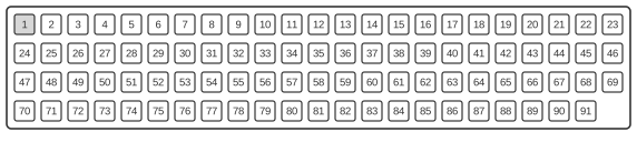 ECU - Electronic Control Unit Connector.
| Pin | name | Signal |
|---|---|---|
| 10 | Ignition Control Module | RPM |
| 13 | Power Ground | Ground |
| 58 | Tachometer Output | Speed |
| 72 | Intake Air Temperature Sensor | Analog |
| 73 | MAP Sensor | Analog |
| 75 | Primary O2 Sensor | Analog |
| 76 | Secondary O2 Sensor | Analog |
| 83 | Engine Coolant Temperature Sensor | Analog |
| 84 | Throttle Position Sensor | Analog |
| 86 | Vehicle Speed Sensor | Speed |
| 91 | Power Ground | Ground |
Notes
The connector is a Mitsubishi proprietary multi-pin unit fitted to the ECU harness on the passenger compartment side of the firewall. Only a subset of the full pin count is listed here; remaining pins cover injector drive, ignition coil, idle speed control, and diagnostic (MUT-II) circuits not detailed on this page. The manual-transmission fitment omits inhibitor switch and shift-solenoid signals present on automatic-transmission variants.
Signals
- Ignition Control Module (pin 10) — RPM reference signal from the crank angle sensor or distributor, used by the ECU to schedule ignition timing.
- Power Ground (pin 13) — main power ground return for the ECU.
- Tachometer Output (pin 58) — engine speed signal sent to the instrument cluster tachometer.
- Intake Air Temperature Sensor (pin 72) — analogue voltage from the IAT sensor; used to correct fuel and ignition calculations for inlet air density.
- MAP Sensor (pin 73) — analogue manifold absolute pressure signal; primary load input to the MFI controller.
- Primary O2 Sensor (pin 75) — narrow-band oxygen sensor signal upstream of the catalytic converter; used for closed-loop fuel trim.
- Secondary O2 Sensor (pin 76) — downstream oxygen sensor signal used for catalyst efficiency monitoring.
- Engine Coolant Temperature Sensor (pin 83) — analogue coolant temperature input; affects warm-up enrichment, idle speed, and fan control.
- Throttle Position Sensor (pin 84) — analogue voltage proportional to throttle plate angle; used for acceleration enrichment and idle detection.
- Vehicle Speed Sensor (pin 86) — speed pulse input from the transmission output shaft; used for idle-up and speed-density correction.
- Power Ground (pin 91) — secondary power ground return for the ECU.
References
- Mitsubishi Lancer CS3A Workshop Manual — Mitsubishi Motors Corporation, engine control / MFI section (no static public host confirmed)