
The Buell DDFI-2 Engine Control Module (ECM) fitted to XB9 and XB12 models from 2003 to 2007 connects via two 12-pin Deutsch DT sockets: a black socket (DT06-12SB) carrying power, ground, and output signals, and a gray socket (DT06-12SA) carrying sensor inputs and serial communications. Both sockets are located under the seat on most XB variants. ECM serial communication operates at TTL voltage levels (0–5 V), not standard RS-232 (±12 V); applying standard RS-232 directly to the diagnostic port risks ECM damage. The DDFI-3 generation (2008–2010 XB and 1125R models) uses a different connector family — two 34-pin AMP Superseal 1.0 mm sockets — and is not covered by this pinout.
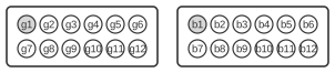
| Pin | Name | Description |
|---|---|---|
| b1 | +12v | |
| b2 | Ground | |
| b3 | Fuel pump | |
| b4 | engine lamp | |
| b5 | Injector front | |
| b6 | Coil front | |
| b7 | Coil rear | |
| b8 | Injector rear | |
| b9 | not connected | for XB9, XB12 unknown |
| b10 | Bank Angle Sensor | |
| b11 | Ground for coil | |
| b12 | Tachometer | |
| solo | gray plug | |
| g1 | +5 for sensors | |
| g2 | TPS | Throttle Position Sensor |
| g3 | Camshaft position sensor | |
| g4 | Oxygen sensor | |
| g5 | +12 | unswitched from battery |
| g6 | Fan | |
| g7 | Ground for sensors | |
| g8 | Vehicle speed sensor | |
| g9 | Engine Temperature Sensor | |
| g10 | Intake Air Temperature sensor | |
| g11 | Serial Receive Data | RX |
| g12 | Serial Transmit Data | TX |
Notes
- The black socket (DT06-12SB) carries switched +12 V ignition power, ECM ground, and all actuator/output lines (fuel pump, injectors, coils, bank angle sensor, tachometer, and check engine lamp).
- The gray socket (DT06-12SA) carries the +5 V sensor supply, sensor return ground, and all sensor input signals together with the serial communications lines.
- ECM serial communication is TTL-level RS-232 (0–5 V). Standard RS-232 interface voltage levels (±12 V) must not be applied; doing so risks permanent ECM damage.
- The 4-pin Deutsch diagnostic (data link) connector (DT04-4P) provides the serial interface: pin 1 = ECM receive (TTL), pin 2 = ground, pin 3 = ECM transmit (TTL), pin 4 = +12 V.
- The ASCII diagram above shows a 6-position view for orientation only; each physical socket has 12 pins (24 pins total across both connectors).
- DDFI-3 ECMs (2008–2010 XB and 1125R models) use two 34-pin AMP Superseal 1.0 mm sockets (black: 2-1437285-3; gray: 3-1437290-9) and have entirely different pin assignments from those shown here.
Signals
Black socket (b-prefix pins)
- b1 — +12 V switched ignition power
- b2 — ECM ground
- b3 — Fuel pump control output
- b4 — Check engine lamp output
- b5 — Front injector control output
- b6 — Front ignition coil control output
- b7 — Rear ignition coil control output
- b8 — Rear injector control output
- b9 — Exhaust valve motor feedback (XB12 models only; not connected on XB9)
- b10 — Bank angle sensor input
- b11 — Coil ground return
- b12 — Tachometer output
Gray socket (g-prefix pins)
- g1 — +5 V sensor supply
- g2 — Throttle position sensor (TPS) signal input
- g3 — Camshaft position sensor input
- g4 — Oxygen sensor input
- g5 — +12 V unswitched (direct battery)
- g6 — Cooling fan control output
- g7 — Sensor ground return
- g8 — Vehicle speed sensor input
- g9 — Engine temperature sensor input
- g10 — Intake air temperature sensor input
- g11 — Serial receive data (ECM Rx, TTL level)
- g12 — Serial transmit data (ECM Tx, TTL level)