
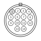
 14 pin SONY BETAMAX female connector.
14 pin SONY BETAMAX male connector.
The Sony 14-pin K-type connector, designated CCK (Camera Cable K-type), is a circular plastic connector of the Hirose RM15 series used on Sony Betamax portapak cameras and decks from the late 1970s onwards. It replaced an earlier 10-pin EIAJ (J-type) format by adding stereo audio channels, a record-review function, and a tally signal line to the camera viewfinder. The HVC-3000C is the Canadian/NTSC variant of the HVC-3000 series; its European counterpart, the HVC-3000P, is confirmed by Sony’s own service documentation to use the same 14-pin K-camera connection. The connector carries composite video in both directions, two channels of audio in each direction, 12 V DC power from the VCR, and several control lines.
| Pin | Signal |
|---|---|
| 1 | Camera video out |
| 2 | Camera video out ground |
| 3 | Camera video in |
| 4 | Camera video in ground |
| 5 | Camera pause. Shorting this pin momentarily to ground will toggle between pause and record or play mode. |
| 6 | Tally signal from the video to the camera. This causes the red light in the view finder to be displayed on the camera. It puts 5v on the pin when the video is in Record Mode, Playback, Audio Dub, x2 or Cue/Review mode. |
| 7 | Camera audio out CH-2 |
| 8 | Record review. When the record review switch is pressed on the camera the video plays the last three seconds of the previous recording for monitoring. |
| 9 | Camera audio out CH-1 |
| 10 | Audio ground |
| 11 | Camera audio in CH-1 |
| 12 | Camera audio in CH-2 |
| 13 | Camera power 12v in. Note, this is internally fused in the VCR |
| 14 | Power ground |
Notes
- Not all cameras implement all available options; feature support varies across Betamax models.
- The physical connector is a Hirose Electric type RM15 series circular plastic connector. The mating inline cable jack is part number RM15TJD-10S and the panel-mount jack is RM15TRD-10S.
- The 12 V power supply on pin 13 is internally fused within the VCR, not within the camera body.
- An alternative pin configuration documented on some cameras reverses the direction of pin 3 (video out from VCR to camera rather than camera video in) and leaves pins 7 and 8 unused; pin 5 may also be labelled “record start/stop” rather than “pause” on those variants. Only connect equipment specifically designed to interface with each other.
- Cameras can exhibit different pause-trigger modes on pin 5: low-default toggle, high-default toggle, or a high-default with an approximately 200 ms negative pulse. The Sony K-type and the earlier EIAJ J-type (10-pin) standards are electrically incompatible without an active converter.
- The CCK-4MP accessory cable adapts the K-type connector to BNC, phono, and mini-plug connections at 1.5 m length.
Signals
- Camera video out (pin 1) — composite video signal from the camera to the VCR; paired with ground on pin 2.
- Camera video out ground (pin 2) — shield/ground return for the pin 1 video signal.
- Camera video in (pin 3) — composite video signal from the VCR to the camera (used for viewfinder feed or electronic viewfinder in some models); paired with ground on pin 4.
- Camera video in ground (pin 4) — shield/ground return for the pin 3 video signal.
- Camera pause (pin 5) — control input; momentarily shorting to ground toggles the VCR between pause and record/play modes. Trigger behaviour (edge, pulse width) varies between camera models.
- Tally (pin 6) — 5 V output from VCR to camera, active when the deck is in Record, Playback, Audio Dub, ×2, or Cue/Review mode; illuminates the red tally lamp in the camera viewfinder.
- Camera audio out CH-2 (pin 7) — second audio channel from camera to VCR (right channel in stereo recording).
- Record review (pin 8) — control input; activating this line causes the VCR to play back approximately the last three seconds of the previous recording for monitoring purposes.
- Camera audio out CH-1 (pin 9) — first audio channel from camera to VCR (left/mono channel in stereo or mono recording).
- Audio ground (pin 10) — common ground return for both audio channel pairs.
- Camera audio in CH-1 (pin 11) — first audio channel from VCR to camera (for audio monitoring in the camera).
- Camera audio in CH-2 (pin 12) — second audio channel from VCR to camera.
- Camera power 12 V in (pin 13) — 12 V DC supply from the VCR to power the camera; the VCR’s internal fuse protects this line.
- Power ground (pin 14) — ground return for the 12 V power supply on pin 13.