
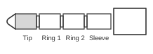
 4 pin 3.5mm (2.5mm) plug connector at the cable (jacks other than 3.5mm may be used).
The 4-pole TRRS (Tip, Ring 1, Ring 2, Sleeve) 3.5 mm concentric plug extends the familiar 3-pole stereo jack with a fourth contact to carry an additional signal — most commonly composite video or a microphone channel. The mechanical design is governed by the Japanese JEITA standard RC-5325A (originally EIAJ RC-5325A, first published 1993), which the Android Open Source Project cites as the reference for headset plug geometry. No single mandatory pinout standard exists for audio/video use: Sony camcorders, Panasonic camcorders, and Aiwa players historically assigned composite video, left audio, right audio, and ground to the four contacts in mutually incompatible orders. The same physical connector body is also used for headsets in two competing configurations — CTIA and OMTP — whose signal assignments differ from both of the camcorder schemes.
| Pin | Sony | Panasonic | Aiwa VCD player |
|---|---|---|---|
| 1 | Left Audio | Right Audio | video in-out |
| 2 | Composite Video | A&V Ground | left audio in-out |
| 3 | A&V Ground | Composite Video | right audio in-out |
| 4 | Right Audio | Left Audio | audio and video signal ground |
Notes
- The 4-pole 3.5 mm TRRS connector shares an identical shell with the standard 3-pole TRS stereo plug; inserting a 3-pole plug into a 4-pole socket shorts Ring 2 to Sleeve, which may mute or damage a connected microphone circuit.
- For audio/video use, no industry-wide pinout standard was ever ratified. Sony, Panasonic, and Aiwa each chose different contact assignments, so a proprietary adapter or cable is required when interconnecting equipment from different manufacturers.
- For headset use, two wiring conventions coexist on 3.5 mm TRRS plugs:
- CTIA / AHJ (the modern default, used by Apple, Samsung, and most Android devices): Tip = Left audio, Ring 1 = Right audio, Ring 2 = Ground, Sleeve = Microphone.
- OMTP (older Nokia, some Sony Ericsson, and Chinese-market devices): Tip = Left audio, Ring 1 = Right audio, Ring 2 = Microphone, Sleeve = Ground. Plugging a CTIA headset into an OMTP socket (or vice versa) will silence audio or prevent the microphone from working.
- The Android AOSP headset specification requires CTIA pinout by default; OMTP is permitted only where legally mandated by local regulation.
- Rated current per Lumberg 1532 02 (JEITA RC-5325A compliant): 1 A; rated voltage 34 V AC/DC; contact resistance ≤ 50 mΩ; operating temperature −20 °C to +70 °C.
- Headset microphone impedance should be 1000 Ω or higher (DC resistance); recommended speaker impedance is 32–300 Ω (minimum 16 Ω) per the Android AOSP specification.
Signals
- Tip (Pin 1) — Left audio output (Sony); Right audio output (Panasonic); Video in/out (Aiwa); Left audio (CTIA/OMTP headset).
- Ring 1 (Pin 2) — Composite video (Sony); Audio and video ground (Panasonic); Left audio in/out (Aiwa); Right audio (CTIA/OMTP headset).
- Ring 2 (Pin 3) — Audio and video ground (Sony); Composite video (Panasonic); Right audio in/out (Aiwa); Ground (CTIA headset) or Microphone (OMTP headset).
- Sleeve (Pin 4) — Right audio output (Sony); Left audio output (Panasonic); Audio and video signal ground (Aiwa); Microphone (CTIA headset) or Ground (OMTP headset).
References
- 3.5 mm headset: Accessory specification — Android Open Source Project (Google)
- Lumberg 1532 02 – 4-pole 3.5 mm jack plug per JEITA RC-5325A — Lumberg Connect GmbH (Belden)