
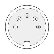
 5 pin DIN male connector.
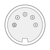 5 pin DIN female connector.
The 5-pin DIN connector follows the mechanical specification of DIN 41524 (now subsumed into IEC 60130-9:2011), sharing the same 13.2 mm outer shell, 1.45 mm pin diameter, and 7 mm pin-circle diameter as all standard circular DIN audio connectors. While originally defined for stereo audio interconnection in European hi-fi equipment, the 5-pin format was widely repurposed by lighting and entertainment technology manufacturers for carrying 0–10 V analogue dimmer control signals, keyboard data, MIDI, and proprietary power/control combinations. In the analogue lighting application documented by ESTA E1.3, four dimmer channels are carried on Pins 1, 3, 4, and 5, with Pin 2 as the 0 V reference ground; no DC power supply pin is provided in this configuration. Signal and voltage assignments vary significantly between manufacturers, so the specific equipment manual must always be consulted before connecting.
| Pin | ||
|---|---|---|
| Application | 1 | 2 |
| Audio (tape) | left input | screen |
| Audio (amp) | left output | screen |
| Audio (source) | left output | screen |
| CCT Regal | +24V DC | -24V DC |
| ETC IR remote focusing unit | ground | PPM data |
| Furse Delta FMX | +24V DC | -24V DC |
| MIDI | not used | screen |
| NSI 4ch analogue | channel 4 | common |
| PC AT keyboard | clock | data |
| Pulsar control | +ve supply | ground |
| Strand GSX / LBX audio in | no connection | ground |
| Teatro Versa-Disc | ch 1 | +15V out |
Notes
The 5-pin DIN plug and socket are keyed by the asymmetric pin layout (180° arc) to prevent reversal. The connector is rated at 60 V AC and 4 A per the Lumberg 0131 series (DIN 41524), but the lighting control and power supply applications listed here may carry DC voltages and currents outside the original audio specification — verify ratings against the specific manufacturer’s documentation before use.
The 5-pin format is mechanically compatible with 3-pin DIN plugs, which engage the three centre pins (Pins 1, 2, and 3); inserting a 3-pin plug into a 5-pin lighting control socket may connect audio ground and signal lines to dimmer control or power pins with unpredictable results.
The 0–10 V analogue dimmer control protocol for the NSI 4-channel application follows ANSI E1.3 (ESTA E1.3-2001): 0 V = fully off, 10 V = fully on, linear response. Controller output impedance must be ≤100 Ω (active) or ≤5 kΩ (passive); receiver input impedance is nominally 100 kΩ.
Signals
Signals vary by application row. The following describe the analogue lighting (NSI 4ch) and MIDI rows:
- channel 4 / common (NSI Pin 1/2) — 0–10 V DC dimmer control signal for channel 4 (Pin 1) and 0 V reference ground (Pin 2), per ESTA E1.3 convention
- +ve supply / ground (Pulsar Pin 1/2) — positive DC supply rail (Pin 1) and 0 V return (Pin 2); voltage level is manufacturer-specific
- not used / screen (MIDI Pin 1/2) — Pin 1 is unconnected in standard MIDI; Pin 2 carries the cable shield
- +24V DC / -24V DC (CCT Regal / Furse Delta Pin 1/2) — bipolar 24 V DC power supply rails; polarity is critical and must not be confused with audio or control signal pins on other applications
References
- DIN EN 60130-9:2011-12 — Connectors for frequencies below 3 MHz, Part 9: Circular connectors for radio and associated sound equipment
- IEC 60130-9:2011 — Connectors for frequencies below 3 MHz, Part 9: Circular connectors for radio and associated sound equipment, 4th edition
- DIN circular connectors reference — Crypto Museum
- Lumberg 0131 Series DIN Connector DIN 41524 — Rapid Electronics