
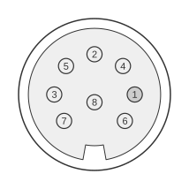
 8 pin DIN male connector.
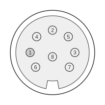 8 pin DIN female connector.
The 8-pin DIN circular connector (DIN 45326, 45° pin spacing) is used in analogue stage-lighting systems to carry six independent 0–10V dimmer-control signals together with a DC supply rail and 0V reference, all within the same 13.2 mm shell defined by IEC 60130-9. It gained widespread adoption in the 1980s and 1990s across European theatrical and architectural dimmer equipment. Two incompatible pinout conventions exist — the Zero 88 / Anytronics / Lightprocessor arrangement and the Pulsar / Clay Paky arrangement — meaning cables and adaptors must be matched to the specific manufacturer’s equipment before connection.
| Pin | |
|---|---|
| Application | 1 |
| Pulsar control | +ve supply |
| Zero88 control | ch 1 |
Notes
- Most manufacturers follow the Zero88 standard shown here.
- Zero 88 / Anytronics / Lightprocessor standard: Pins 1–6 carry channels 1–6 (0 to +10V analogue control signal); Pin 7 carries the DC desk supply voltage (+18 to +25V, maximum 100 mA); Pin 8 is the 0V reference. The Zero 88 Betapack 2 provides a switchable +20V or −20V supply on Pin 7 and auto-senses the control polarity.
- Pulsar / Clay Paky standard: Pin 1 = +V DC supply; Pin 2 = 0V reference; Pins 3–8 = channels 1–6. Connecting Pulsar equipment to a Zero 88 rack without an adaptor cable will place channel signals onto power pins and is potentially hazardous.
- Polarity: Strand equipment uses negative polarity (0 to −10V control); Zero 88, Anytronics, Pulsar, and Lightprocessor equipment uses positive polarity (0 to +10V). Mixing polarities on a shared Pin 7 supply line can blow fuses; all packs connected together must be set to the same polarity.
- Protocol: The 0–10V analogue control protocol is standardised as ANSI E1.3-2001 (ESTA E1.3). 0V = fully off; 10V = full on; response is linear. Active controller output impedance must be ≤100Ω and source at least 2.0 mA continuously; receiver input impedance is nominally 100 kΩ (±20%).
- Connector mechanics: The shell outer diameter is 13.2 mm; pin diameter is 1.45 mm; pins are arranged on a 7.0 mm diameter virtual circle at 45° spacing (DIN 45326). Rated for 60 Vac / 4 A per IEC 60130-9 / Lumberg 0131 series data.
- Locking: The 8-pin DIN used for stage lighting is a locking variant; the Zero 88 Betapack 2 manual specifies an 8-pin locking DIN connector for the analogue control input.
Signals
- Ch 1–6 — Independent 0–10V analogue dimmer-control signals, one per channel; 0V = off, 10V = full brightness, linear response (Zero 88 / Anytronics / Lightprocessor: Pins 1–6; Pulsar / Clay Paky: Pins 3–8).
- +V supply — DC power rail supplied by the dimmer desk to the dimmer pack; Zero 88 standard: +18 to +25V at 100 mA maximum on Pin 7; Pulsar standard: Pin 1.
- 0V — Common reference / return for both the control signals and the DC supply rail (Zero 88 standard: Pin 8; Pulsar standard: Pin 2).
References
- IEC 60130-9:2011 — Connectors for frequencies below 3 MHz, Part 9: Circular connectors for radio and associated sound equipment (4th edition)
- DIN EN 60130-9:2011-12 — Connectors for frequencies below 3 MHz, Part 9: Circular connectors for radio and associated sound equipment
- Zero 88 Betapack 2 Owner’s Information Manual, Third Issue, October 1998
- Zero 88 Betapack 2 (Socketed MCB) Specification Sheet, Issue 3, October 2003
- DIN Circular Connectors Reference — Crypto Museum
- Lumberg 0131 Series DIN Connector product range — Rapid Electronics